Interface to FEA#
Computer-aided engineering, particularly finite element analysis (FEA), plays a critical role in digitally verifying product performance before conducting physical tests and initiating production. In lattice design, creating the geometry and mesh presents significant challenges for FEA. Artisan offers basic outputs for lattice mesh and can also calculate the signed distance field value for given spatial points. This capability significantly enhances the efficiency of assembling FEA models and supports the customized development of FEA applications for lattice structures.
Mesh Export#
User may utilize the meshing function to create the volumetric mesh for various application, such as CFD analysis. Here we introduce the export of 1D and 2D elements for mechanical analysis, that dramatically reduces the efforts on meshing and computational time. The exporting mesh in the current version supports the strut and TPMS based conformal lattice. User may export the shell elements for TPMS type lattice, or the beam element for strut lattice. Only a simple additional setup is required in the conformal lattice definition file. Here is an example (the example file: .//Test_json//FEAMesh//GenSphericalConformalMesh.json) below showing the exports of the beam elements for a conformal lattice infilled structure. Please note that, the fineness of the element is controlled by the resolution setup.
{
    "Setup": {
        "Type": "Sample",
        "Sample": {
            "Domain": [[-10.0, 10.0], [-10.0, 10.0], [-10.0, 10.0]],
            "Shape": "Box"
        },
        "Geomfile": "",
        "Rot": [0.0, 0.0, 0.0],
        "res": [0.1, 0.1, 0.1],
        "Padding": 1,
        "onGPU": false,
        "memorylimit": 1073741824000
    },
    "WorkFlow": {
        "1": {
            "Gen_SphericalMesh": {
                "num_elem": [3, 10, 4],
                "r_range": [3.0, 8.0],
                "theta_range": [0.3, 0.7],
                "ori": [0.0, 0.0, 0.0],
                "Normal": [1.0, 1.0, 0.0],
                "Mesh_file": ".//Test_json//FEAMesh//SphericalMesh.med",
                "phi_range": [0.2, 0.8]
            }
        },
        "2": {
            "Add_Lattice": {
                "la_name": ".//Test_json//FEAMesh//GenSphericalConformalMesh.mld",
                "size": [3.0, 3.0, 3.0],
                "thk": 0.2,
                "Rot": [0.0, 0.0, 0.0],
                "Trans": [0.0, 0.0, 0.0],
                "Inv": false,
                "Fill": false,
                "Cube_Request": {}
            }
        },
        "100000": {
            "Export": {
                "outfile": ".//Test_results/SphericalMesh_ConformalLattice.stl"
            }
        }
    },
    "PostProcess": {
        "CombineMeshes": true,
        "RemovePartitionMeshFile": false,
        "RemoveIsolatedParts": true,
        "ExportLazPts": true
    }
}
And the definition file of the conformal lattice, GenSphericalConformalMesh.mld, is as below.
{
 "type": "ConformalLattice",
 "definition": {
    "meshfile": ".//Test_json//FEAMesh//SphericalMesh.med",
    "ExportFEAMeshFile": ".//Test_json//FEAMesh//SpherieFEAMesh.inp",
    "la_name": "BCCubic"
    }
}
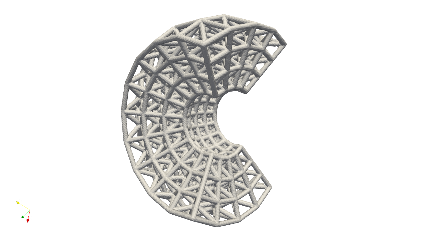
The parameter ExportFEAMeshFile defines the export mesh file. In this case, the mesh is exported in Abaqus inp file format. This is a text file, and user can use any text editor open and edit the content. In geneal the lattice structure shall look like the one below.
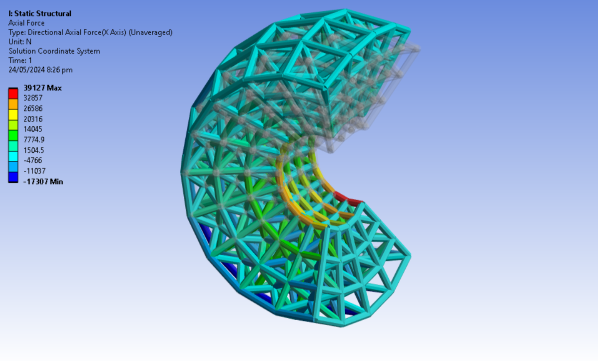
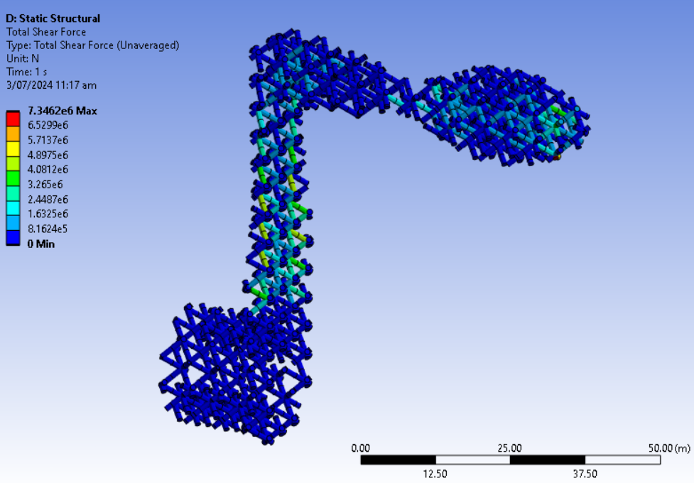
Then we could import the inp file into the Ansys workbench, for example, and conduct further analysis. For example, one below shows the axial forces on the beam elements subject the load force on top end and fixed bottom end boundary conditions.
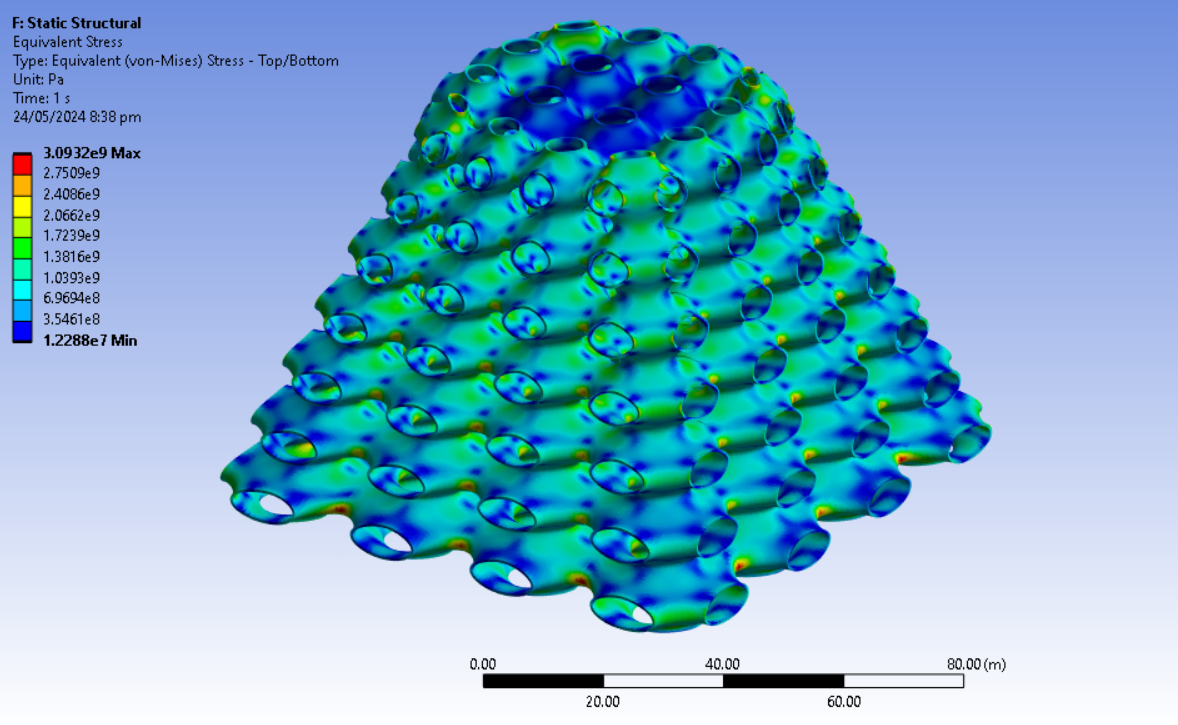
Similarly, user may find the TPMS example (the example file: .//Test_json//FEAMesh//Parts02_Export_TPMS_conformal.json). Same as the strut lattice, the TPMS shell elements can be imported into any major FEA solver for further analysis. Below shows a simple compression case that the bottom edges were fixed and the load applied on top edges.
Alternatively, users can use the keyword Gen_ConformalLatticeMesh to generate a conformal mesh based on the existing definition file. The example below demonstrates how to create the FEA mesh for a periodic lattice using Gen_ConformalLatticeMesh and Proc_Mesh_Trim. The process is straightforward: first, generate a conformal lattice within a domain box that contains the geometry. Then, apply Proc_Mesh_Trim to trim the lattice to match the geometry’s boundary. User may find the examples under the folder .//Test_json//FEAMesh//MeshTrim for strut lattice, and .//Test_json//FEAMesh//MeshTrim_TPMS for the TPMS lattice. Here we use TPMS lattice infill as an example.
{
    "Setup": {
        "Type": "Geometry",
        "Sample": {
            "Domain": [[0.0, 1.0], [0.0, 1.0], [0.0, 1.0]],
            "Shape": "Box"
        },
        "Geomfile": ".//sample-obj//crank_handle.stl",
        "Rot": [0.0, 0.0, 0.0],
        "res": [0.1, 0.1, 0.1],
        "Padding": 4,
        "onGPU": false,
        "memorylimit": 1073741824000
    },
    "WorkFlow": {
        "1": {
            "Gen_BoxMesh": {
                "Normal": [0.0, 0.0, 1.0],
                "z_angle": 0.0,
                "ori": [-11.0, -11.0, -80.0],
                "x_range": [0.0, 25.0],
                "y_range": [0.0, 76.0],
                "z_range": [0.0, 79.0],
                "Mesh_file": ".//Test_json//FEAMesh//MeshTrim_TPMS//BaseMesh.med",
                "num_elem": [8, 20, 20]
            }
        },
        "2": {
            "Gen_ConformalLatticeMesh": {
                "definition_file": ".//Test_json//FEAMesh//MeshTrim_TPMS//ConformalLattice.mld",
                "out_meshfile": ".//Test_json//FEAMesh//MeshTrim_TPMS//BaseMeshConformal.med",
                "size": [1.0, 1.0, 1.0],
                "Rot": [0.0, 0.0, 0.0]
            }
        },
        "3": {
            "Proc_Mesh_Trim": {
                "inp_meshfile": ".//Test_json//FEAMesh//MeshTrim_TPMS//BaseMeshConformal.med",
                "Geomfile": "",
                "tol": 0.01,
                "num_beam_refinement": 2,
                "remove_short_beams": true,
                "elem_type": "Triangle",
                "out_meshfile": ".//Test_json//FEAMesh//MeshTrim_TPMS//TrimMesh.stl"
            }
        }
    },
    "PostProcess": {
        "CombineMeshes": true,
        "RemovePartitionMeshFile": false,
        "RemoveIsolatedParts": true,
        "ExportLazPts": false
    }
}
Gen_ConformalLatticeMesh generates the conformal mesh, and Proc_Mesh_Trim trims the conformal mesh in the box domain to the given geometry boundary. The parameters for the Gen_ConformalLatticeMesh are listed below.
Parameter |
Details |
|---|---|
|
the file path to the |
|
file path to export the conformed mesh. |
|
this parameter with the global resolutions is used to calculate the triangle mesh fineness. The smaller division of resolutions over size leads to a finer mesh. |
|
Rotation applied on the unit lattice. This setup intends to change the orientation of the unit lattice. |
The parameters for the Proc_Mesh_Trim are listed below.
Parameter |
Details |
|---|---|
|
imports the beam or triangle elements from |
|
file path to the geometry which used for trimming the mesh. |
|
file path for the export mesh file. |
|
Numbers of refinements applies to the beam elements, if |
|
Currently only supports |
|
If true, the short beam (less then |
|
The tolerance that mesh snaps to the geometry, inside of function, this number also will be used for identifying the small elements. |
In this case, we shall have the mesh like below.
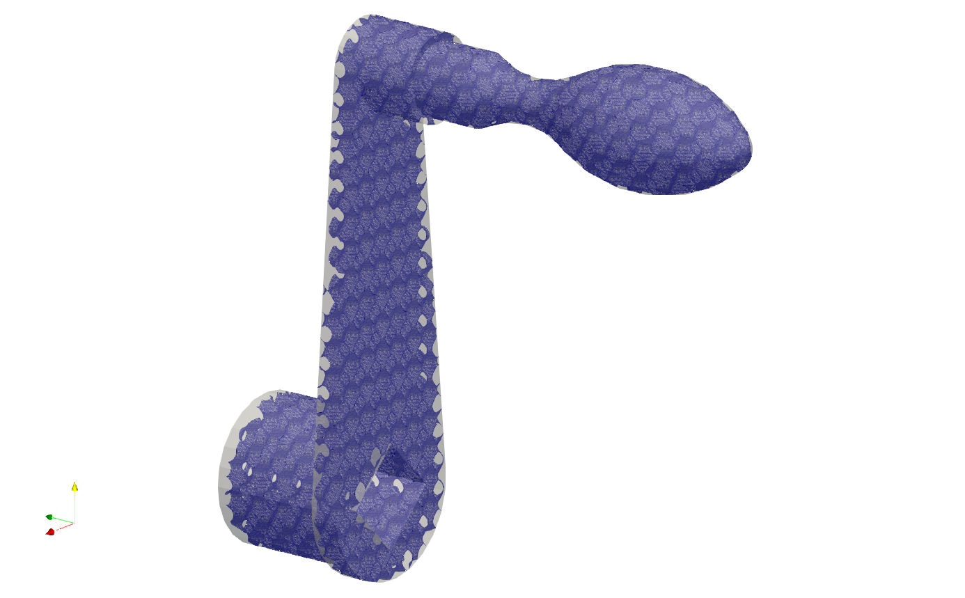
Similarly user may apply the same work flow to get strut elements (The strut lattice example is at .//Test_json//FEAMesh//MeshTrim).
SDF Export#
Users can calculate the signed distance field (SDF) for specified spatial points. The provided spatial coordinates are used to evaluate the SDF values, which represent the minimum distance between each point and the nearest geometry surface. A negative value indicates that the point is inside the geometry, while a positive value indicates that it is outside. A value of zero denotes that the point lies precisely on the geometry surface. In practical applications, these points can either be nodes within a mesh or specified in a CSV file format - users may refer to the relevant documentation on field operations.
{
    "Setup": {
        "Type": "Sample",
        "Sample": {
            "Domain": [[-10.0, 10.0], [-10.0, 10.0], [-10.0, 10.0]],
            "Shape": "Box"
        },
        "Geomfile": "",
        "Rot": [0.0, 0.0, 0.0],
        "res": [0.1, 0.1, 0.1],
        "Padding": 1,
        "onGPU": false,
        "memorylimit": 1073741824000
    },
    "WorkFlow": {
        "1": {
            "Gen_SphericalMesh": {
                "num_elem": [3, 10, 4],
                "r_range": [3.0, 8.0],
                "theta_range": [0.3, 0.7],
                "ori": [0.0, 0.0, 0.0],
                "Normal": [1.0, 1.0, 0.0],
                "Mesh_file": ".//Test_json//FEAMesh//SphericalMesh.med",
                "phi_range": [0.2, 0.8]
            }
        },
        "2": {
            "Add_Lattice": {
                "la_name": ".//Test_json//FEAMesh//GenSphericalConformalMesh.mld",
                "size": [3.0, 3.0, 3.0],
                "thk": 0.2,
                "Rot": [0.0, 0.0, 0.0],
                "Trans": [0.0, 0.0, 0.0],
                "Inv": false,
                "Fill": false,
                "Cube_Request": {}
            }
        },
        "3": {
            "Evaluate_Points": {
                "Inp_meshfile": ".//Test_json//FEAMesh//SphericalMesh.med",
                "Export_file": ".//Test_json//FEAMesh//Points_SDF.csv"
            }
        },
        "100000": {
            "Export": {
                "outfile": ".//Test_results/SphericalMesh_ConformalLattice.stl"
            }
        }
    },
    "PostProcess": {
        "CombineMeshes": true,
        "RemovePartitionMeshFile": false,
        "RemoveIsolatedParts": true,
        "ExportLazPts": true
    }
}
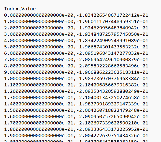
In the work flow item 3, the keywords Evaluate_Points defines the input spatial data points, for example, in a mesh "Inp_meshfile":".//Test_json//FEAMesh//SphericalMesh.med", and the calculated results are stored in the csv file "Export_file": ".//Test_json//FEAMesh//Points_SDF.csv". It has to note that, only csv file extension is accepted as the export file format.
User shall see the results similar to the results below. The export csv file contains two column, index and value. Each row corresponds to the input nodal index.
Limitations#
Here are a few limitations and recommended pre-processing steps before assembling the FEA model:
Mesh Quality: The exported beam and shell element meshes must be reviewed using a professional FEA pre-processor. The mesh may contain low-quality elements, and users should remove defective elements or perform re-meshing if necessary.
Node Merging: Merging nodes is highly recommended, as the mesh is exported through a lattice array and neighboring elements may not be connected.