Field Operation#
User may use field, defined externally or with geometric features, to enhance the lattice infill. In the field operation, the concept refers to use external data or spatial field to enhance (e.g. thickening) to lattice thickness, or to detect geometry features and therefore enhance the lattice infill using the geometry feature lines.
External Field Enhancement#
Often the engineer/designer would like to design a component that accommodates engineering analysis results, such as finite element stress analysis etc., or try to introduce a thicker material layer at the areas suffered higher system loads. In Artisan, these regionally specified design change is considered as a spatially varying field that is added to the existing design field, or being an input variable affecting the local lattice design.
Artisan can read external field (i.e. a data cloud in 3D spatial space) as input and perform high nonlinear interpolation on the field, and use the field to modify local material thickness. Here we use a bending steel bar as an example to demonstrate how to incorporate with external field data, for instance, in this case, a von Mises stress results generated from Ansys mechanical software. Assuming one side of long steel bar is fixed, the force is applied downward on the bottom edge of the other side. The deformation and stress distribution is shown as below.

As shown here, the left hand side surface was fully fixed, and the force applied on the right hand side edge. Therefore the higher stress was observed around the fixation, and gradually reduced towards the right hand side. The stress field can be exported as data cloud, including nodal coordinate with X, Y and Z, and the nodal corresponding von Mises stress values. In practice, Artisan reads the csv file that looks like below. CSV files are text files with information separated by commas, saved with the extension .csv. The file has to be separated by commas and Artisan will skip the first row and first colum, but read the data from second row and second colum.

In order to incorporate with above data, we could define a lattice fill with field strength on the local material thickness as the JSON below.
   {"Setup":{  "Type" : "Geometry",
               "Geomfile": ".//sample-obj//Bar//Bar.stl",
               "Rot" : [0.0,0.0,0.0],
               "res":[0.25,0.25,0.25],
               "Padding": 1,
               "onGPU": false,
               "memorylimit": 16106127360
               },
"WorkFlow":{
         "1": {"Add_Lattice":{
                   "la_name": "BCCubic", "size": [10.0,10.0,10.0], "thk":0.5, "Rot":[0.0, 0.0, 0.0], "Trans":[0.0, 0.0, 0.0],
                   "Inv": false, "Fill": true, "Cube_Request": {}
                   }
              },
         "2":{"OP_OffsetField":{"Max_Offset":1.5,"Min_Offset":0.001,
              "FieldFile":".//sample-obj//Bar//fielddata.csv", "Fill": true}},
         "3":{"Export": {"outfile": ".//Test_results/Bar_FieldScale.stl"}}
          },
"PostProcess":{"CombineMeshes": true,
               "RemovePartitionMeshFile": false,
               "RemoveIsolatedParts": false,
               "ExportLazPts": false}
   }
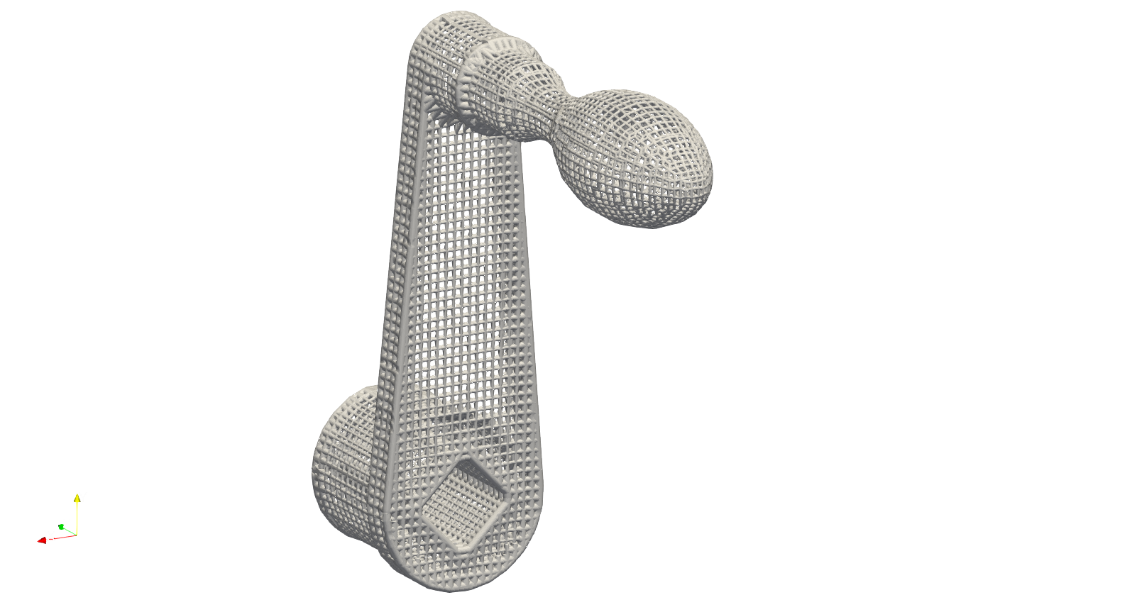
The item 2 in the WorkFlow shows a new keywords OP_OffsetField. It takes the maximum and minimum values in the field data and perform linear interpolation local material thickness offset corresponding to the field value data. In this case, for example, the maximum offset 1.5 mm (i.e. the keywords Max_Offset defined) will be added to the region where has the maximum stress data, whereas the minimum field value (i.e. the keywords Min_Offset defined) 0.001 mm is applied to the spot with lowest stress value. The offset value which the field values lies between max and min will be interpolated using the Min_Offset and Max_Offset. the results are as shown below. User can find this example Bar_FieldOffset.json at the Test_json folder.

The top and lower lattices where close to the fixation side were thickened in corresponding to the field values.
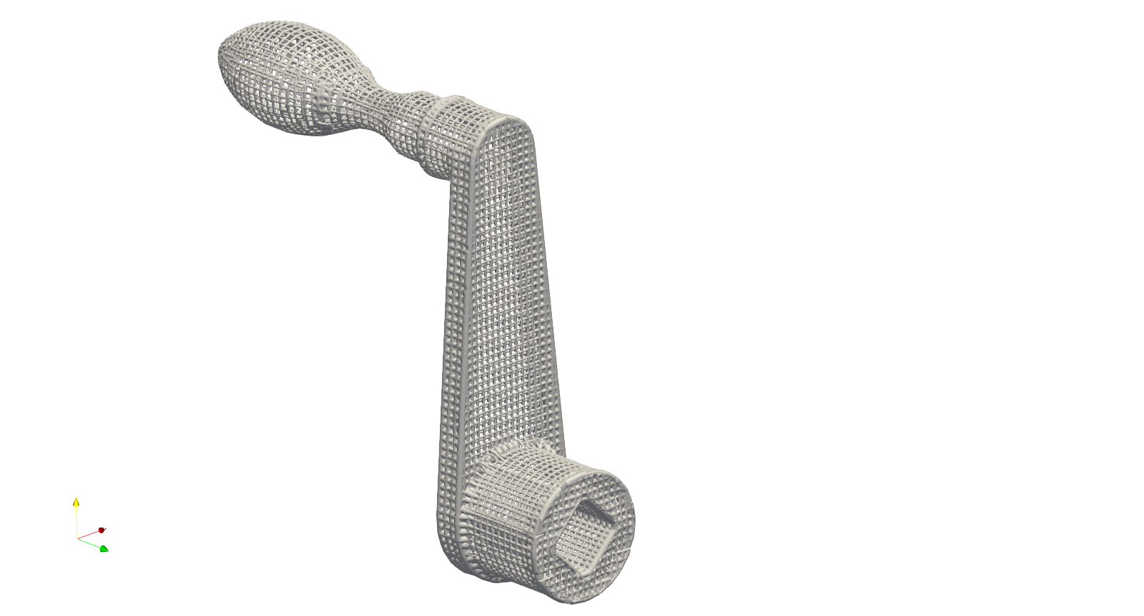
The field offset operation certainly can apply to other lattice, such as conformal or mesh lattices. Here we use the steering knuckle as example to demonstrate a simple design work flow to reduce the weight and reinforce the local lattice structure. Please note that, this example is only for demonstrating the application of software functionalities, and has no implication on any products.

Steering knuckle is a piece of cast iron made component that ideally should be lightweight in order to improve vehicle’s efficiency and handling. Below is comparison between the original component design and mesh lattice filled geometry.


The steering knuckle has to be verified by a series load cases in order to meet the structural integrity criterion. The stress distribution is therefore generated by applying the boundary conditions which reflects the loads in these scenarios. This stress filed was then exported as a csv file, and later imported as inputs for the design calculation. User may find the full JSON in the file SteeringKnuckle_Mesh_Infill_LR.json.
{"Setup":{ "Type" : "Geometry",
           "Geomfile": ".//sample-obj//SteeringKnuckle//SteeringKnuckle.stl",
           "Rot" : [0.0,0.0,0.0],
           "res":[0.3,0.3,0.3],
           "Padding": 2,
           "onGPU": false,
           "memorylimit": 1610612736000000
           },
"WorkFlow":{
     "1": {"Add_Lattice":{
               "la_name": ".//Test_json//SteeringKnuckle//SteeringKnuckle_Mesh_Infill_LR.mld", "Rot":[0.0, 0.0, 0.0], "Trans":[0.0, 0.0, 0.0],
               "size": [8.0,8.0,8.0], "thk":0.5, "Inv": false, "Fill": false,
               "Cube_Request": {}
               }
          },
     "2":{"OP_OffsetField":{"Max_Offset":2.5,"Min_Offset":-0.1,
                            "FieldFile":".//sample-obj//SteeringKnuckle//SteeringKnuckle_vonMisesStress.csv", "Fill": true}},
     "3":{"Export": {"outfile": ".//Test_results/SteeringKnuckle_Mesh_Infill_OPField_3.stl"}}
      },
"PostProcess":{"CombineMeshes": true,
               "RemovePartitionMeshFile": false,
               "RemoveIsolatedParts": false,
               "ExportLazPts": false}
}
The mesh lattice definition file .//Test_json//SteeringKnuckle//SteeringKnuckle_Mesh_Infill_LR.mld has a simple setup.
{
     "type": "MeshLattice",
     "definition": {
               "meshfile": ".//sample-obj//SteeringKnuckle//SteeringKnuckle.msh"
     }
}
The exterior surface has been trimmed by the geometric surface for clean and smooth finish. User may try the un-trimmed design by using "Fill": false in the keyword "OP_OffsetField". The field value file .//sample-obj//SteeringKnuckle//SteeringKnuckle_vonMisesStress.csv stores the sptial data points and the corresponding field value, in this case, the von Miese stress at various nodal points in the FEA mesh. It has to note that, the mesh in the FEA analysis does not have to be same as the lattice mesh. Two meshes has no relationship and can be complete two different mesh.
The overall comparison is presented below.


Local comparison on the high stress areas showed the locally reinforced and thickened materials on the component.


An comparison from the other side.


Please note that, above examples takes large data set as interpolation inputs and can be a very time consuming operation. More data points included in the field data could result longer computational time. The current field operation function can only handle the material thickening operation. We will work on the features and algorithm by extending the function to the lattice size and lattice types.
Geometry Feature Enhancement#
Geometry frequently incorporates various distinctive features along its edges, like sharp edges, which typically serve functional purposes. In design, emphasizing these features can be crucial for improving mechanical performance. Artisan offers straightforward methods to identify and capture these key features and it transforms these captured feature lines into field based operations that enhance the functional features.
Sharpe Edge Enhancement#
Artisan has the keywords OP_EdgeEnhance to identify the given mesh sharp edges, and build the cylindrical shape offset fields in order to enhance the material thickness around the cylindrical volume. The one below is a simple example of enhancing the box edges by capturing triangle edges that satisfy the certain criteria of features angle. The JSON file can be find at FieldOpt\Box_EdgeEnhance.json.
{"Setup":{ "Type" : "Geometry",
           "Geomfile": ".//sample-obj//cube_1mm.ply",
           "Rot" : [0.0,0.0,0.0],
           "res":[10.0,10.0,10.0],
           "Padding": 1,
           "onGPU": false,
           "memorylimit": 1073741824000
           },
"WorkFlow":{
     "1": {"Add_Lattice":{
               "la_name": "Cubic",
               "size": [100.0,100.0,100.0], "thk":20.0,
               "Rot":[0.0,0.0,0.0], "Trans":[0.0,0.0,0.0],
               "Inv": false, "Fill": false,
               "Cube_Request": {}
               }
          },
     "2":{
           "OP_EdgeEnhance":{"Angles":[1.57, 1.6],
                             "r": 100.0,
                             "max_offset": 100.0,
                                               "min_offset": 0.0,
                                               "meshfile": ".//sample-obj//cube_1mm.ply",
                                               "MergeNodes": true,
                                               "Fill": true
                           }
         },
     "3":{"Export": {"outfile": ".//Test_results/Box_EdgeEnhance.stl"}}
      },
"PostProcess":{"CombineMeshes": true,
           "RemovePartitionMeshFile": false,
           "RemoveIsolatedParts": false,
           "ExportLazPts": false}
}
The keywords OP_EdgeEnhance captures the given geometry’s edges angles formed by their two neighboring triangles. Here is the details of each parameter.
Parameter |
Details |
|---|---|
|
this parameter defines the range of edge feature angle in radians; |
|
it is a float number defining the influence radius; |
|
the maximum thickness offset that happened at the edge. The offset level will be reduced in accordance with the influence radius |
|
the minimum thickness offset happens at the end of the influence radius; |
|
a string of the path to the mesh file contains the geometry, mesh has to be a cluster of triangles forming the geometric boundary. |
|
a bool type parameter, if |
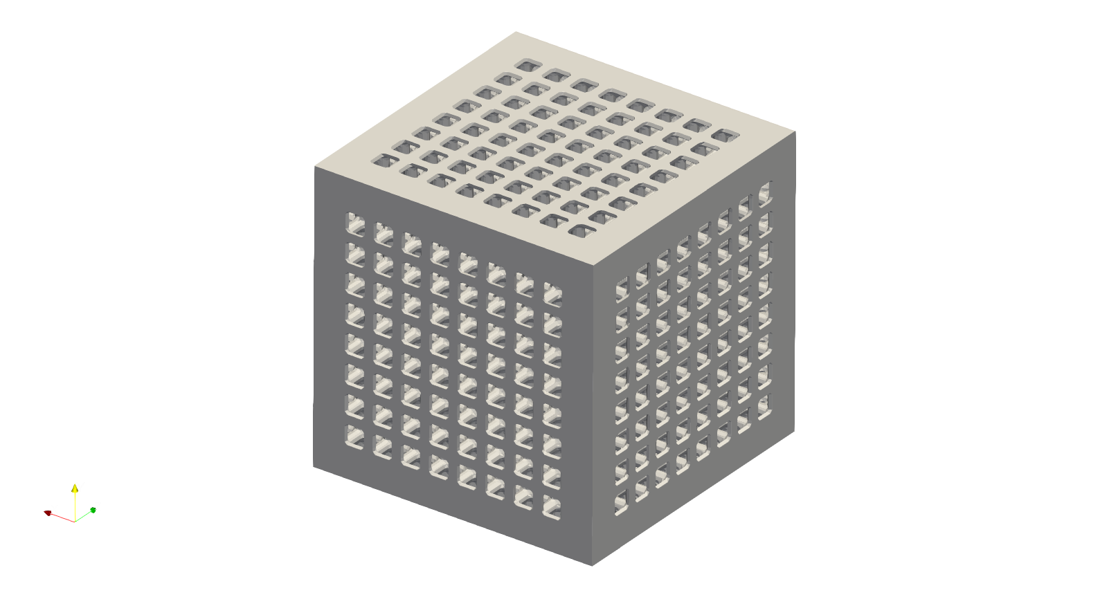
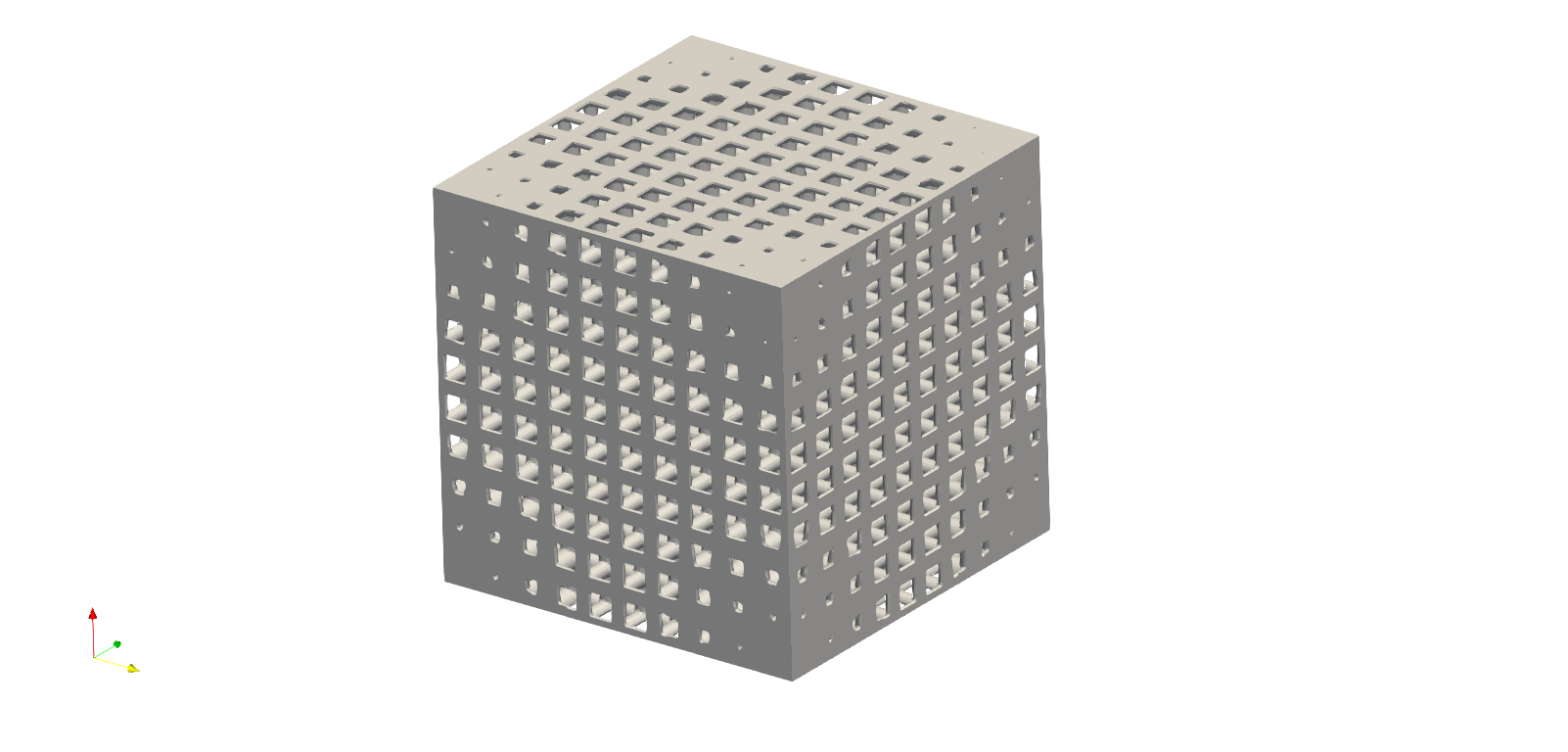
The box contains the edge enhancement is presented below. The box sharp edges which forms the shape has been dramatically enhanced with the cubic lattice infill.
The example at FieldOpt\Crankhandle_EdgeEnhance.json shows a more complicated case that captures the sharp edge and thickening the surface lattice accordantly.
Corner Enhancement#
Corner features can be identified through the keywords OP_CornerEnhance. Corners are considered as the center points of the sphere which is the influence volume in this keywords. The offset field is then added to the lattice field in order to varying the material thickness. A simple example (user may find it at FieldOpt\Box_EdgeEnhance.json) of enhancing the 4 corner of a box shape is shown in the JSON below.
{"Setup":{ "Type" : "Geometry",
           "Geomfile": ".//sample-obj//cube_1mm.stl",
           "Rot" : [0.0,0.0,0.0],
           "res":[5.0,5.0,5.0],
           "Padding": 4,
           "onGPU": false,
           "memorylimit": 1073741824000
           },
"WorkFlow":{
     "1": {"Add_Lattice":{
               "la_name": "Cubic",
               "size": [100.0,100.0,100.0], "thk":20.0,
               "Rot":[0.0,0.0,0.0], "Trans":[0.0,0.0,0.0],
               "Inv": false, "Fill": false,
               "Cube_Request": {}
               }
          },
     "2":{
           "OP_CornerEnhance":{"k": 0.04,
                               "threshold": 0.95,
                               "r": 400.0,
                               "max_offset": 40.0,
                                                    "min_offset": 0.0,
                                                    "meshfile": ".//sample-obj//cube_1mm.stl",
                                                    "Fill": true,
                               "param": {"sigma_factor": 0.025,
                                         "grid_factor": 5}
                           }
         },
     "3":{"Export": {"outfile": ".//Test_results/Box_CornerEnhance.stl"}}
      },
"PostProcess":{"CombineMeshes": true,
           "RemovePartitionMeshFile": false,
           "RemoveIsolatedParts": false,
           "ExportLazPts": false}
}
The keywords OP_CornerEnhance has similar parameters as OP_EdgeEnhance. Generally the parameters helps the algorithm to identify the corner on the given mesh, and the calculation parameters that may need turning for better capturing of the corner.
Parameter |
Details |
|---|---|
|
the sensitivities of algorithm for capturing the corner, ranging from 0.04 to 0.06; |
|
the sharpness of the corner, ranging from 0.01 to 0.99. |
|
it is a float number defining the influence radius of spherical volume; |
|
the maximum thickness offset that happened at the edge. The offset level will be reduced in accordance with the influence radius |
|
the minimum thickness offset happens at the end of the influence radius; |
|
a string of the path to the mesh file contains the geometry, mesh has to be a cluster of triangles forming the geometric boundary. |
|
contains two parameters, |
The algorithm relies on the fineness of the field (i.e. the resolution), and identifies the corner locations using field grid mesh, therefore may not exactly at the location of the mesh surface. The JSON above produce the results below.
Mathematical Expression#
User may conduct manipulation of the lattice thickness on the lattice field directly through the keywords OP_Expr_OffsetField. For instance, the JSON (the example file: .//Test_json//FieldOpt//Box_FieldOffsetExpr.json) below shows the periodic changes on the lattice thickness.
{"Setup":{    "Type" : "Geometry",
              "Geomfile": ".//sample-obj//cube_1mm.stl",
              "Rot" : [0.0,0.0,0.0],
              "res":[5.0,5.0,5.0],
              "Padding": 4,
              "onGPU": false,
              "memorylimit": 1073741824000
      },
"WorkFlow":{
        "1": {"Add_Lattice":{
                  "la_name": "SchwarzPrimitive",
                  "size": [100.0, 100.0, 100.0],
                  "thk":10.0, "Rot":[0.0, 0.0, 0.0], "Trans":[0.0, 0.0, 0.0],
                  "Inv": false,
                  "Fill": true,
                  "Cube_Request": {}
                  }
             },

        "2":{"OP_Expr_OffsetField":
              {
                "expr": "5 * sin(2 * pi * x / 200)",
                "Fill": false
                }
            },
        "3":{"Export": {"outfile": ".//Test_results/Box_FieldOffset_Expr.stl"}}
         },
"PostProcess":{"CombineMeshes": true,
              "RemovePartitionMeshFile": false,
              "RemoveIsolatedParts": true,
              "ExportLazPts": false}
}
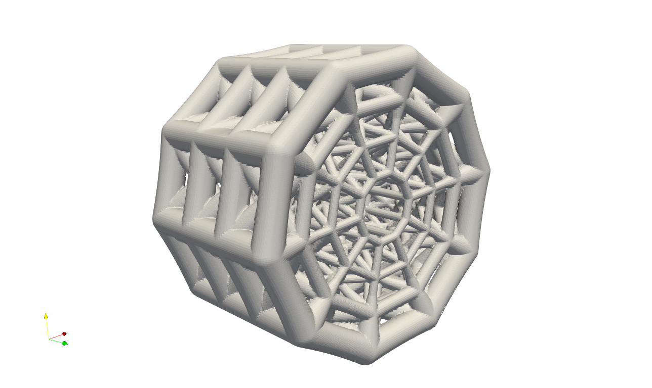
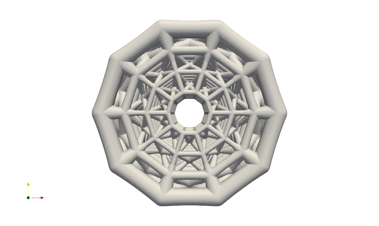
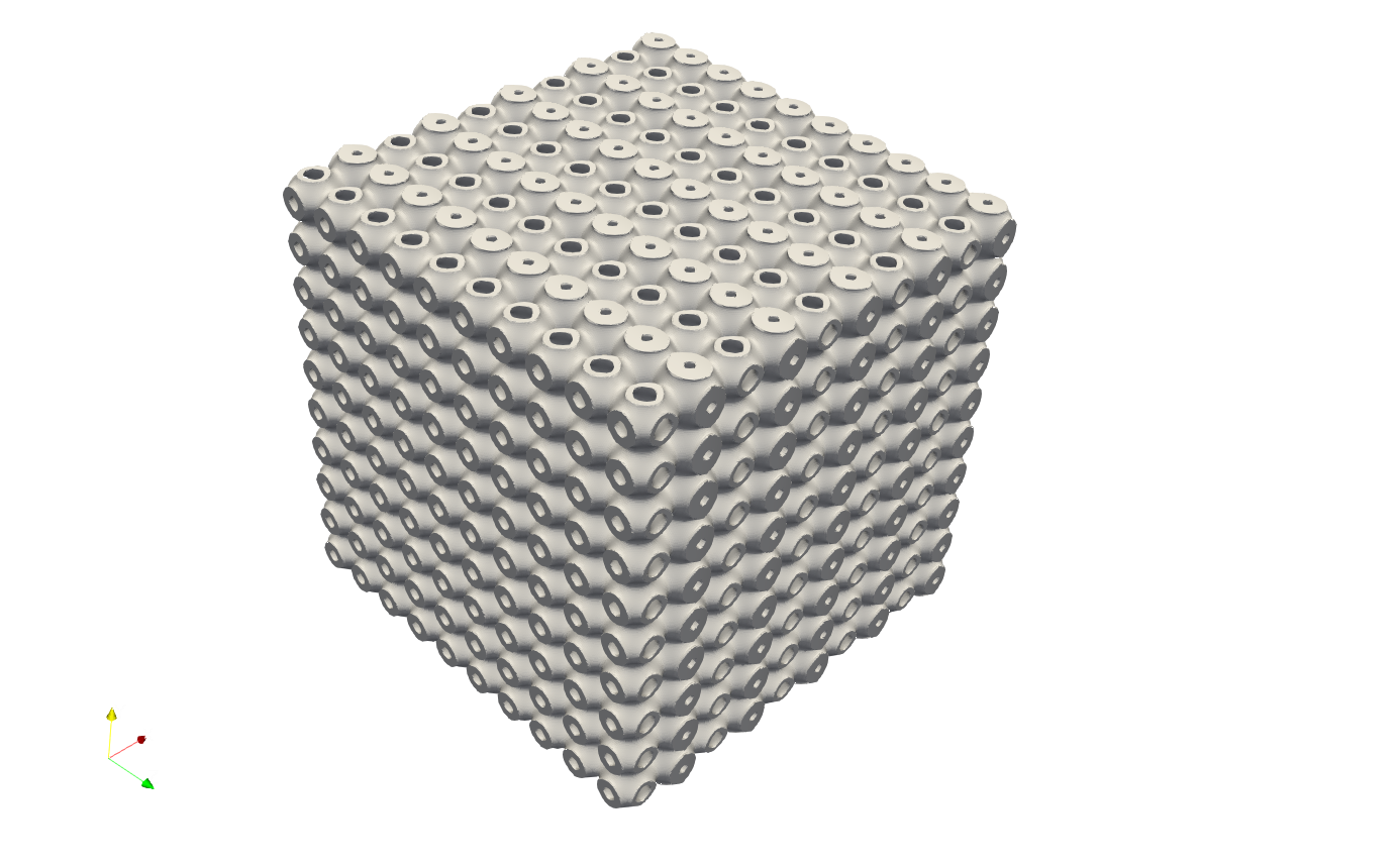
The parameter expr defines the mathematical expression. Similar to the customized TPMS, the back end of the function is supported by the package numexpr (online manual: https://numexpr.readthedocs.io/en/latest/user_guide.html). The parameter Fill tells whether the cut operation with the geometric field conducts. As a result, the following shape should be produced. The thickness of the TPMS were changed periodically along with x-axis.
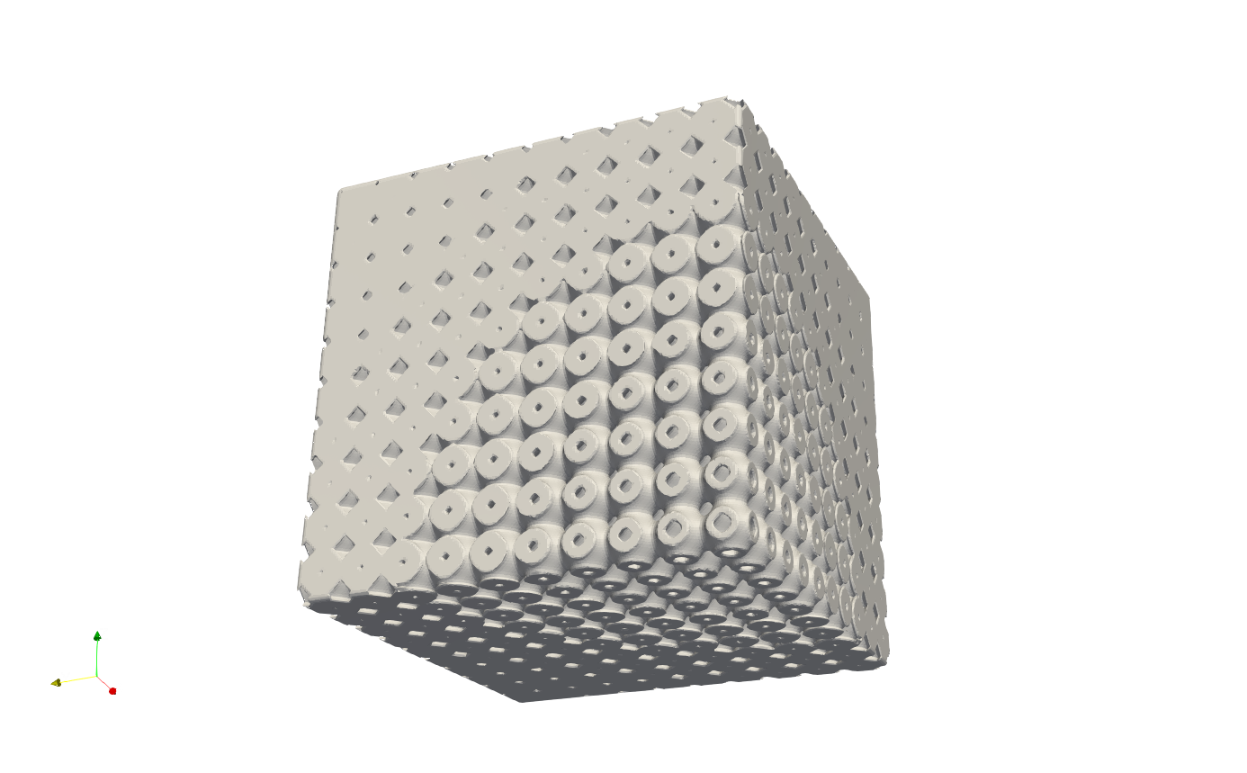
We certainly could also try make an attractor type thickness change, for example (the example file: .//Test_json//FieldOpt//Box_FieldOffsetExpr_attractor.json), by defining "expr": "(1 - sqrt(x**2+y**2+z**2)/200)*3.5".
Geometry Field#
Artisan supports geometry field operations, enabling precise control of local material thickness in design. By defining influence volumes with geometric shapes, designers can create gradual, controlled variations in material thickness across parts or structures. JSON below shows the basic example of how to use geometry field to control the locally varying material thickness. User may find this example at :code:.//Test_json//FieldOpt//CylinderGradeLattice.json`.
 {
   "Setup": {
       "Type": "Sample",
       "Sample": {
           "Domain": [[-10.0, 10.0], [-10.0, 10.0], [-10.0, 15.0]],
           "Shape": "Box"
       },
       "Geomfile": "",
       "Rot": [0.0, 0.0, 0.0],
       "res": [0.1, 0.1, 0.1],
       "Padding": 1,
       "onGPU": false,
       "memorylimit": 1073741824000
   },
   "WorkFlow": {
       "1": {
           "Gen_CylindricalMesh": {
               "num_elem": [3, 10, 3],
               "r_range": [2.0, 8.0],
               "phi_range": [0.0, 1.0],
               "ori": [0.0, 0.0, -2.0],
               "Height": 10.0,
               "Normal": [0.0, 0.0, 1.0],
               "Mesh_file": ".//Test_json//PrimitiveDesign//CylindricalMesh.med"
           }
       },
       "2": {
           "Add_Lattice": {
               "la_name": ".//Test_json//PrimitiveDesign//GenCylindricalConformalMesh.mld",
               "Rot": [0.0, 0.0, 0.0],
               "Trans": [0.0, 0.0, 0.0],
               "Inv": false,
               "Fill": false,
               "Cube_Request": {},
               "thk": 0.25,
               "size": [5.0, 5.0, 5.0]
           }
       },
       "3": {
           "OP_FieldOffset_GeomField": {
               "Name": "Cylinder",
               "Paras": {
                   "pa": [0.0, 0.0, -10.0],
                   "r": 10.0,
                   "pb": [0.0, 0.0, 30.0]
               },
               "min_val": 0.0,
               "min": -5.0,
               "max_val": 1.0,
               "max": 0.0,
               "min_max_opt": [0.0, 0.0],
           }
       },
       "9999": {
           "Export": {
               "outfile": ".//Test_results/CylindricalMesh_ConformalLattice.stl"
           }
       }
   },
   "PostProcess": {
       "CombineMeshes": true,
       "RemovePartitionMeshFile": false,
       "RemoveIsolatedParts": true,
       "ExportLazPts": true
   }
}
The keyword OP_FieldOffset_GeomField controls the field operation by defining a geometry that could be either a standard shape or an external shape. This keyword generates the signed distance field of the geometry, and then remaps the user defined max and min and linearly interpolates the offset values from max_val to min_val.
Parameter |
Details |
|---|---|
|
shares the same definition to the parameter |
|
shares the same definition to the parameter |
|
the maximum value in the SDF of the geometry; |
|
the minimum value in the SDF of the geometry; |
|
the maximum offset value that remapped to the |
|
the minimum offset value that remapped to the |
|
A list of two numbers controlling the maximum and minimum values. If either number is greater than 0, it overrides the corresponding input and is taken directly from the SDF (Signed Distance Field). |