Customization#
Artisan integrates a number of lattice design, including:
Strut Lattice |
TPMS Lattice |
Strut Lattice Tetrahedron domain |
|---|---|---|
Cubic, BCCubic, VertexOcta, BC, FCCubic, EdgeOcta, StarTet, Dodecahedron, Auxetic |
SchwarzDiamond, SchwarzPrimitive, FischerKoch, Neovius, Lidinoid, Gyroid |
Rhombic, Star, Icosahedral, Voronoi, Kagome, Tetrahedron |
We plan to expand the list mentioned above in future developments. Strut and TPMS lattices are generally used in hexahedral domains, which have 6 faces and 8 nodes, such as a cube. Strut lattices in tetrahedral domains are primarily utilized in the generation of conformal lattices when tetrahedral meshes are provided. It’s important to note that Artisan does not check the lattice domain types during the filling process, but be aware that using mismatched lattice types can lead to unexpected results. Lattices in tetrahedral domains will be discussed in a later section.
We understand that this might not satisfy all users’ requirements at certain stages. Artisan is capable of incorporating users’ lattice definitions into the design. Users can define a lattice in three different ways:
Strut lattice, i.e. topological connections;
Surface lattice, i.e. mathematical/implicit equations such as TPMS;
Geometric shape, i.e. a file contains geometry mesh.
In practice, users only need to set the la_name parameter in all keywords to the file containing the definitions. Please note that this file must have a .txt extension. Artisan automatically detects the customized definition and interprets its content. The definition file contains a JSON structure that specifies the type of customized lattice and how it is defined.
We have presented a few examples with the Add_Lattice keyword. Users can extend this feature to the Lin_Interpolate, HS_Interpolate, and Attractor keywords.
Strut Lattice#
Defining a strut lattice requires the nodal coordinates, and topological conductivities, e.g. connection between two nodes. We use a simple geometry fill to demonstrate this functionality. Below is main example JSON which calls the user defined lattice.
{"Setup":{  "Type" : "Geometry",
            "Geomfile": ".//sample-obj//shell_1_of_bdd_.stl",
            "Rot" : [0.0,0.0,0.0],
            "res":[0.5,0.5,0.5],
                        "Padding": 1,
            "onGPU": false,
            "memorylimit": 16106127360
            },
 "WorkFlow":{
      "1": {"Add_Lattice":{
                "la_name": ".//Test_json//CustomLattice_Strut.txt", "size": [8.0,8.0,8.0], "thk":1.2, "Rot":[0.0, 0.0, 0.0], "Trans":[0.0, 0.0, 0.0],
                "Inv": false, "Fill": true, "Cube_Request": {}
                }
           },
      "2":{"Export": {"outfile": ".//Test_results/BingDunDun_Infill_CustomStrut.stl"}}
       },
 "PostProcess":{"CombineMeshes": true,
            "RemovePartitionMeshFile": false,
            "RemoveIsolatedParts": true,
            "ExportLazPts": false}
}
The parameter la_name in the keywords Add_Lattice became a file path that links to the custom strut lattice definition. The definition in the file is showed below. In this case, we defines the strut lattice type, and nodes coordinates and the conductivities. Note that the node coordinates shall define with from 0 to 1 mm in x, y and z direction. The parameter "ladomain" defines the lattice in a hexahedron lattice domain, i.e. "Hex", a domain defined by 6 faces and 8 nodes.
{
  "type": "strut",
   "definition": {
                   "pts":
                          [[1.0, 1.0, 0.0],
                           [1.0, 1.0, 1.0],
                           [0.0, 1.0, 1.0],
                           [0.0, 1.0, 0.0],
                           [0.0, 0.0, 0.0],
                           [0.0, 0.0, 1.0],
                           [1.0, 0.0, 1.0],
                           [1.0, 0.0, 0.0]],
                   "cnnt":[[0, 1],[0, 3],
                           [3, 2],[2, 1],
                           [1, 6],[0, 7],
                           [3, 4],[2, 5],
                           [7, 4],[7, 6],
                           [6, 5],[4, 5],
                           [0, 5],[1, 4],
                           [2, 7],[3, 6]],
                   "ladomain" : "Hex"
                 }

}
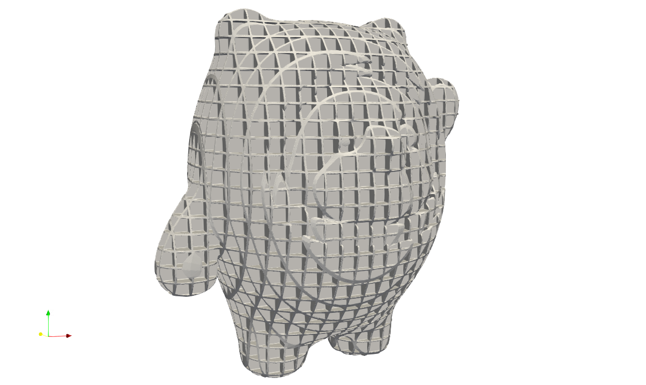
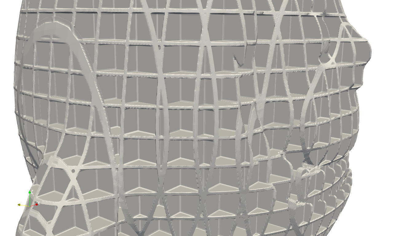
Above example shall produce the filled results like below. Yes, it is filled by the BCCubic lattice. User may try different nodes locations and/or conductivities.

TPMS Lattice#
Users can define a TPMS surface through its implicit equation and apply a thickness to generate a lattice unit. The example below shows a typical definition of a customized TPMS lattice:
{
 "type": "TPMS",
 "definition": {
 "unit_x_len": "2*pi",
 "unit_y_len": "2*pi",
 "unit_z_len": "2*pi",
 "expr": "cos(x)+cos(y)+cos(z)",
 "ladomain" : "Hex"}
}
In this definition, we defined an implicit equation
The user must specify the unit length for the equation in each direction. In this example, it is set to 2*pi, corresponding to \(2\pi\). Artisan uses the numexpr package to evaluate mathematical equations and expressions. Please refer to the official documentation for a complete list of supported mathematical symbols and functions:
Github: pydata/numexpr
Documentation: https://numexpr.readthedocs.io/en/latest/user_guide.html
Once defined, Artisan can generate a TPMS-style infill. Note that the size and thk parameters in the Add_Lattice keyword automatically determine the lattice unit size and thickness.

User may define grid field driven TPMS surface lattice. For the grid field, user may refer to chapter Grid Field Container. The example of using grid field can be find at .\Test_json\FieldTPMS\Cube_FieldTPMS.json.
{"Setup":{      "Type" : "Sample",
              "Sample": {"Domain" : [[0.0,10.0],[0.0,10.0],[0.0,10.0]], "Shape": "Box"},
              "Geomfile": "",
              "Rot" : [0.0,0.0,0.0],
              "res":[0.1,0.1,0.1],
              "Padding": 2,
              "onGPU": false,
              "memorylimit": 1073741824000
              },
 "WorkFlow":{
        "1": {
              "OP_Fit_GridField":{
                   "inp_ptFieldFile": ".//Test_json//FieldTPMS//cube_points_linear_jittered.csv",
                   "out_gridFieldFile": "FrequencyField"
               }
                         },
        "2": {"Add_Lattice":{
                  "la_name": ".//Test_json//FieldTPMS//CustomLattice_FieldTPMS.txt",
                  "size": [2.0, 2.0, 2.0], "thk":0.1, "Rot":[0.0, 0.0, 0.0], "Trans":[0.0, 0.0, 0.0],
                  "Inv": false, "Fill": true,
                  "Cube_Request": {}
                  }
             },
        "999":{"Export": {"outfile": ".//Test_results//FieldTPMS.stl"}}
         },
 "PostProcess":{"CombineMeshes": true,
              "RemovePartitionMeshFile": false,
              "RemoveIsolatedParts": true,
              "ExportLazPts": false}
}
and the customized lattice definition CustomLattice_FieldTPMS.txt is below.
{
  "type": "TPMS-Field",
  "definition": {
    "unit_x_len": "2*pi",
    "unit_y_len": "2*pi",
    "unit_z_len": "2*pi",
    "expr": "cos(FrequencyField*x)+cos(FrequencyField*y)+cos(FrequencyField*z)",
    "ladomain": "Hex"
}
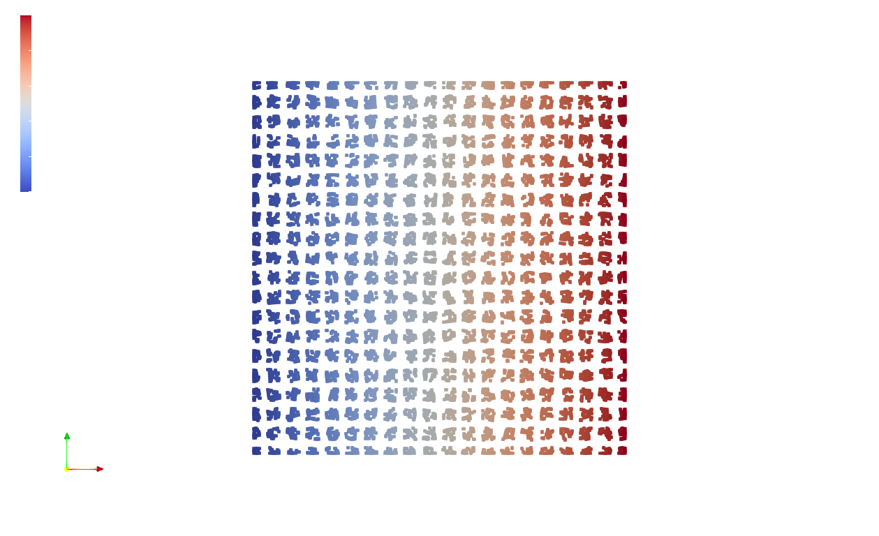
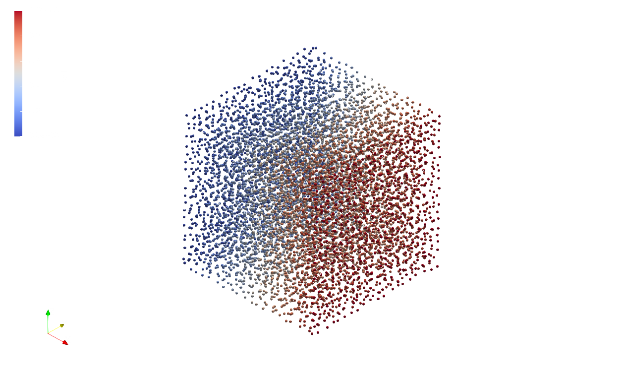
The keyword OP_Fit_GridField fits the external data points into the grid field container, and the mathematical expression of the TPMS therefore refers the variable FrequencyField in the definition. Belows shows the original data points which forms a scaler field that controls the size of the local lattice.
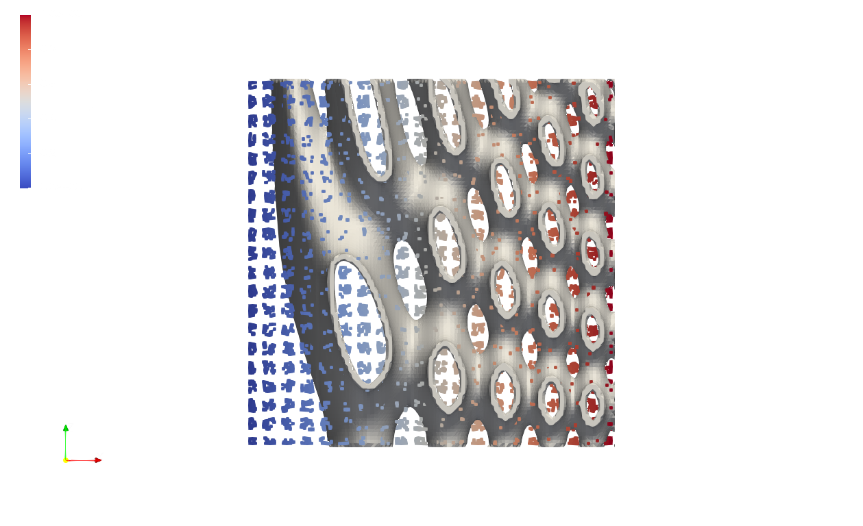
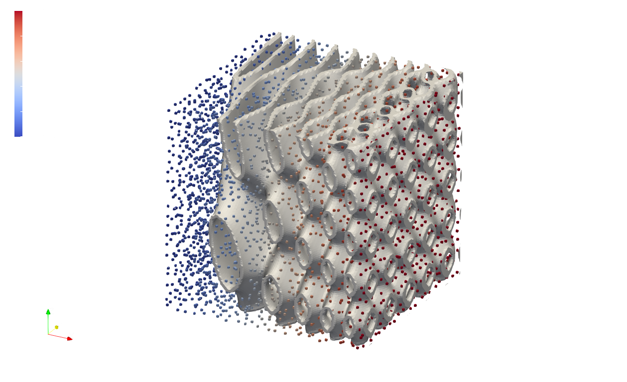
Below shows TPMS lattice with spatially varying lattice size overlays the data points.
Geometry Lattice#
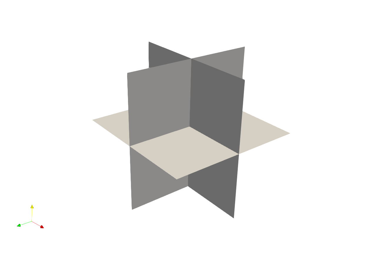
Artisan also supports user defined geometry infill. It meant the infill can be a geometry shape that made from other software. For example, we would like to put the following geometric shape as infill.

To fill the geometry with this shape, we could define it like below.
{
 "type": "Geom",
 "definition": {
                 "file": ".//sample-obj//boxframe.obj",
                 "ladomain" : "Hex"
                }
}
We could have following results.

More details here.

The thickness of the geometric shape lattice is adjustable through defining the parameter thk. The initial inputs will be considered as 0.0, the negative value of thk shrinks the shape, whereas the positive value expands the lattice unit. The thickness of the given shape has different definition in conformal lattice, please refer to conformal lattice section for more details.
One need clarify that above example "type":"Geom" defines a closed, water tight and solid body mesh geometry. Artisan also supports the single surface mesh defined geometry by change the parameter "type" to "Geom-Plate". For instance, we have the following single surface mesh.
By change the custom lattice definition, we should have the following results. Please note that the thickness of lattice is defined by the calling keyword parameter Thk.
{
 "type": "Geom-Plate",
 "definition": {
                 "file": ".//sample-obj//SuperCross.stl",
                 "ladomain" : "Hex"
                }
}
Lattice Container#
The customized lattice may be defined within the main workflow, rather than in the external files. The example file .//Test_json//LatticeContainer//LatticeContainer_CustomizedStrut.json demonstrate how to define a customerized lattice defintion in the workflow.
{"Setup":{  "Type" : "Geometry",
            "Geomfile": ".//sample-obj//shell_1_of_bdd_.stl",
            "Rot" : [0.0,0.0,0.0],
            "res":[0.5,0.5,0.5],
                        "Padding": 1,
            "onGPU": false,
            "memorylimit": 16106127360
            },
 "WorkFlow":{
      "1": {
        "Define_Lattice":{
            "la_name": "CustomStrut",
            "definition":{
                "type": "strut",
                "definition": {
                   "pts":
                          [[1.0, 1.0, 0.0],
                           [1.0, 1.0, 1.0],
                           [0.0, 1.0, 1.0],
                           [0.0, 1.0, 0.0],
                           [0.0, 0.0, 0.0],
                           [0.0, 0.0, 1.0],
                           [1.0, 0.0, 1.0],
                           [1.0, 0.0, 0.0]],
                   "cnnt":[[0, 1],[0, 3],
                           [3, 2],[2, 1],
                           [1, 6],[0, 7],
                           [3, 4],[2, 5],
                           [7, 4],[7, 6],
                           [6, 5],[4, 5],
                           [0, 5],[1, 4],
                           [2, 7],[3, 6]],
                   "ladomain" : "Hex"
                 }
            }
         }
      },
      "2": {"Add_Lattice":{
                "la_name": "CustomStrut", "size": [8.0,8.0,8.0], "thk":1.2, "Rot":[0.0, 0.0, 0.0], "Trans":[0.0, 0.0, 0.0],
                "Inv": false, "Fill": true, "Cube_Request": {}
                }
           },
      "999":{"Export": {"outfile": ".//Test_results/BingDunDun_Infill_CustomStrut.stl"}}
       },
 "PostProcess":{"CombineMeshes": true,
            "RemovePartitionMeshFile": false,
            "RemoveIsolatedParts": true,
            "ExportLazPts": false}
}
The keyword Define_Lattice accommodates the lattice definition. The following keyword Add_Lattice just simply referred to the naming id - the value of parameter la_name. Table below shows the explanation of the parameters.
Parameter |
Details |
|---|---|
|
A string based naming id for referencing the lattice definition. |
|
The entire block of the custom lattice definition. This can be the mesh lattice or conformal lattice definition as well. |
Once lattice defined, the naming id can be referred any keyword that requires the lattice name or definition. No extenral file definition is required.