Meshing 01#
One way of creating lattice infill is mapping the given lattice unit, such strut, TPMS or geometry, into the infill domain as defined by mesh. User may refers to the Conformal Lattice 01 generation section for details. This section summarized the basic integrated mesher functions. All examples here you should be able to find under the folder Test_jsonMeshLattice, or otherwise specified locations. For the primitive shape mesh, such as sphere, user shall refer to the chapter Primitive Design.
Cartesian Mesher#
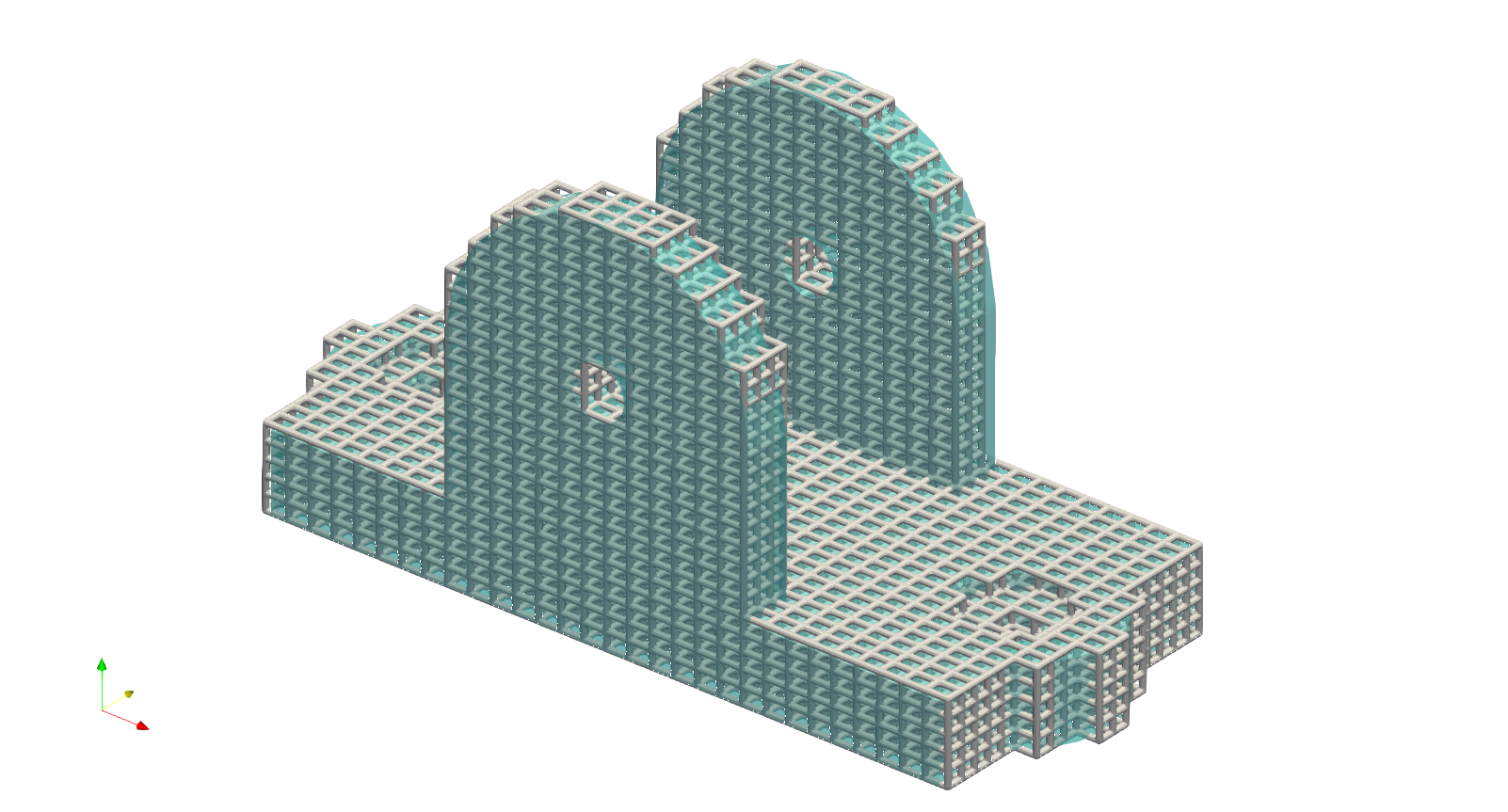
Artisan has an integrated Cartesian mesher, which can be used to generate an approximated conformal hex mesh. It’s important to note that this mesher employs a projection method to align the boundary mesh nodes with the surface of the given geometry. As a result, the output in some cases may not be a true conformal hex mesh. Even if the boundary mesh is significantly distorted, users can still utilize the resulting mesh to create a lattice that adheres to the given boundary shape. For an example of generating hex-dominant elements on a geometry, users can refer to the file CartesianHexMesh\GenCartesianHexMesh.json.
{"Setup":{  "Type" : "Geometry",
            "Geomfile": ".//sample-obj//telecope_tripode_base.stl",
            "Rot" : [0.0,0.0,0.0],
            "res":[0.1, 0.1, 0.1],
                    "Padding": 4,
            "onGPU": false,
            "memorylimit": 16106127360000000
            },
"WorkFlow":{
      "1": {
           "Gen_BasicCartesianHexMesh":{
             "num_elem": [40, 25, 25],
             "x_range": [0.0, 60.0],
             "y_range": [0.0, 27.0],
             "z_range": [0.0, 26.0],
             "ori":[-48.0,-20.0,0.0],
             "Normal": [0.0,0.0,1.0],
             "z_angle": 0.0,
             "Meshfile": ".//Test_json//CartesianHexMesh//TripodeHexMesh.med",
             "Geomfile": ".//sample-obj//telecope_tripode_base.stl",
             "numPrjLayers": 1,
             "LayerDepth": 1.0,
             "numCoverNodes": -1
            }
           },
      "2": {
           "Add_Lattice":{
                "la_name": ".//Test_json//CartesianHexMesh//Tripod_HexInfill.mld",
                            "size": [1.0, 1.0, 1.0], "thk":0.2,
                            "Rot": [0.0, 0.0, 0.0], "Trans":[0.0, 0.0, 0.0],
                            "Inv": false, "Fill": false,
                "Cube_Request": {}
                }
           },
      "3": {
           "Export": {"outfile": ".//Test_results//Tripod_HexInfill.stl"}
           }
               },
"PostProcess":{"CombineMeshes": true,
            "RemovePartitionMeshFile": false,
            "RemoveIsolatedParts": true,
            "ExportLazPts": true}
}
The keywords Gen_BasicCartesianHexMesh calls the function of producing the Cartesian mesh. Its parameters are very similar to block mesh generation. User may refer to the section Primitive Design for details. Here only lists the additional parameters.
Parameter |
Details |
|---|---|
|
this parameter defines the targeting geometry, and it is a string defining the path to the file. |
|
an integer number defines the number of layer projections. If |
|
the depth of each layer. if |
|
an integer number of nodes covered in the boundary layer. It shall be between |
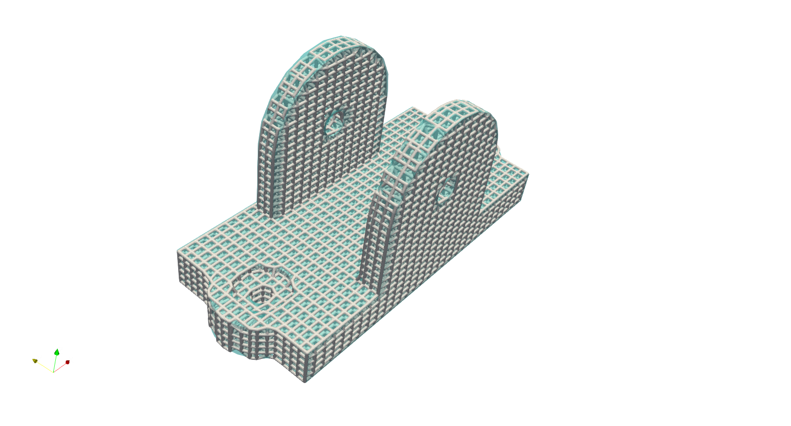
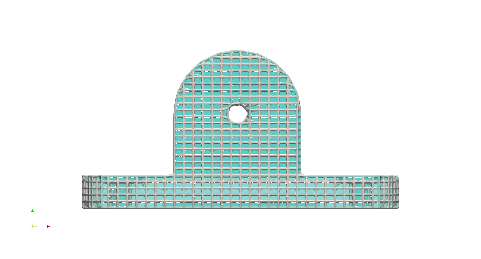
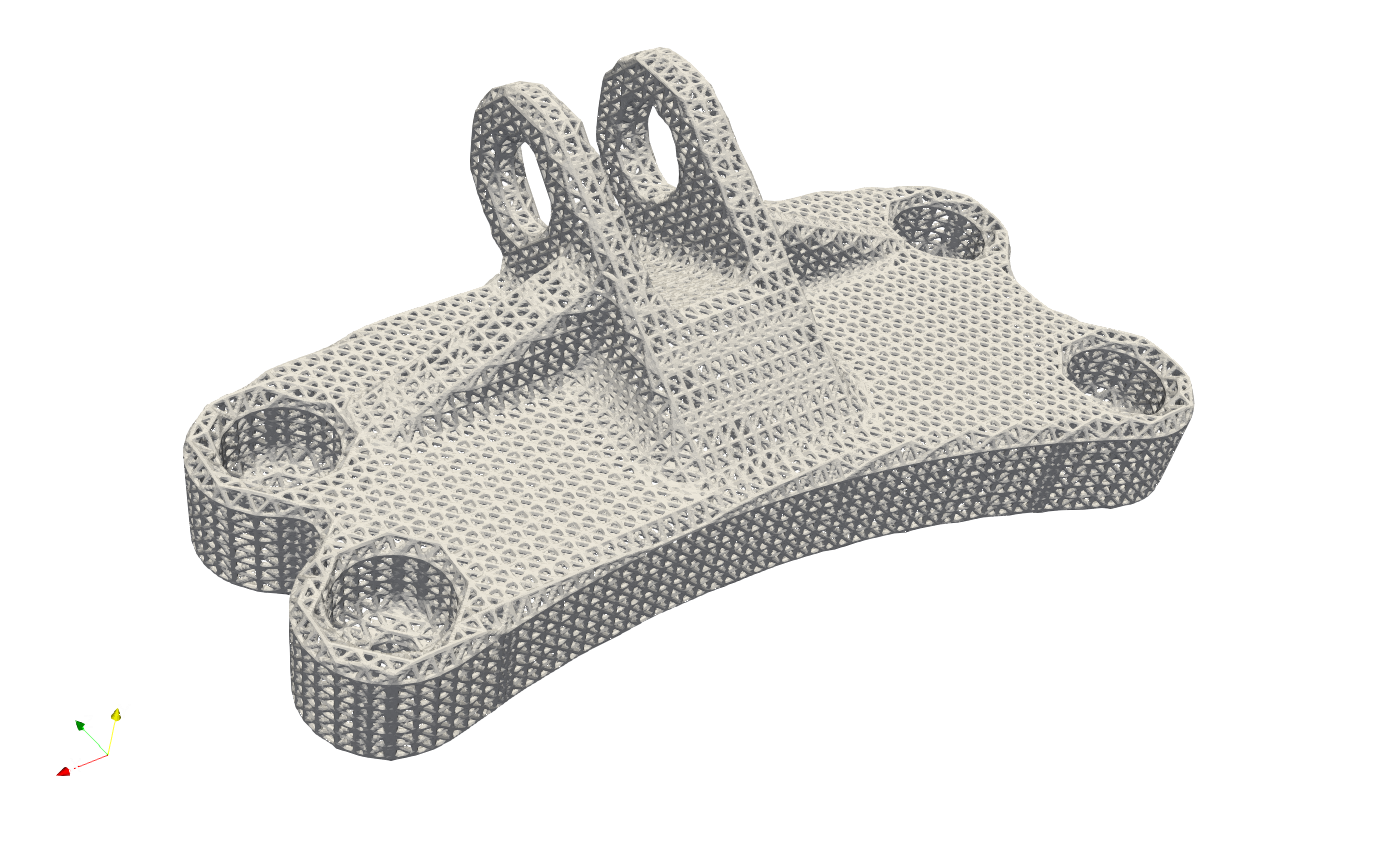
In the JSON example above, the center of the hex element was used to determine whether the element should be removed. Users can experiment with different removal strategies to see how the parameter numCoverNodes impacts the final results. In the following example, the parameter numPrjLayer is set to 0. The resulting jig-saw shaped element cluster demonstrates how the Cartesian mesh approximates the outline of the geometry. While this projection method may not guarantee high-quality hex elements, it does produce a hex-dominant mesh that can be utilized for hex lattice infill.
Above example produce the following results. The tripod geometry is overlapped with the cubic lattice using the generated mesh.
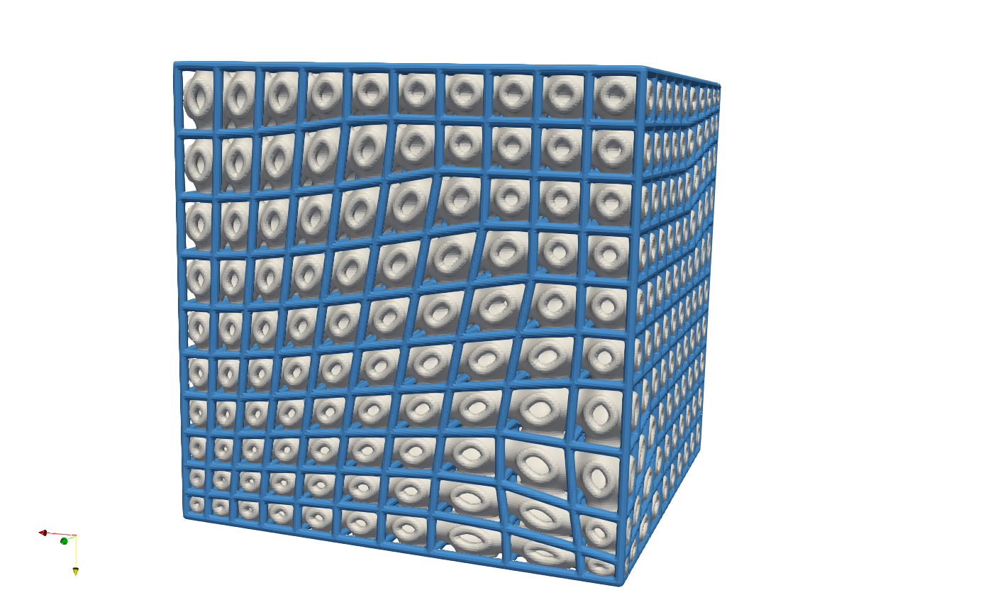
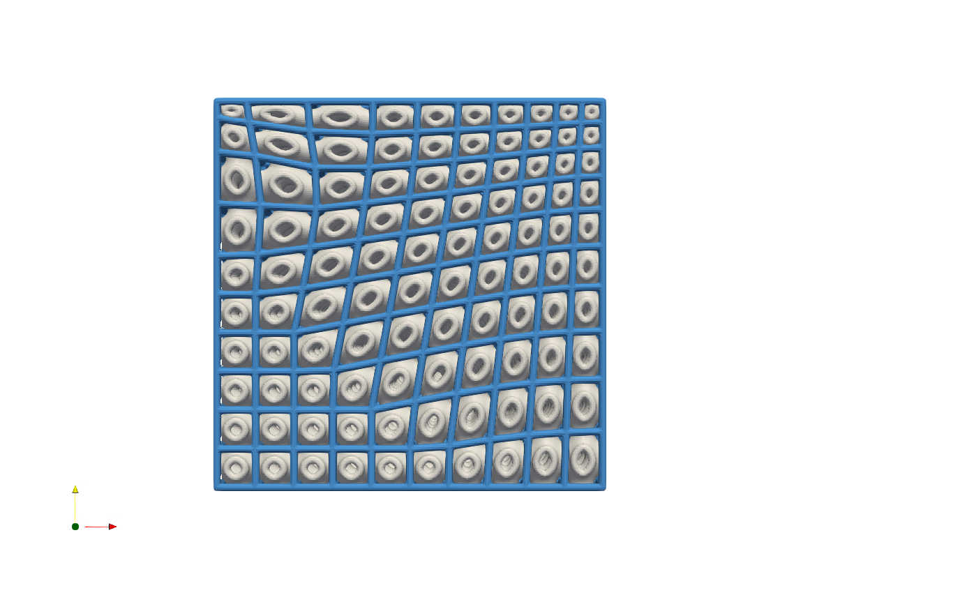
The mesh can be generated with varying mesh sizes while maintaining the same topological connections. The function Gen_BasicCartesianHexMesh_MultiSize allows for the inclusion of spatial attractors to facilitate local mesh deformation. An illustrative example can be found in the file Box_Conformal_MultiSize/GenCartesianHexMesh_MultiSize.json. In this example, a box-shaped region contains three local attractors, each generating a ball-shaped potential field that influences the local mesh size and deformation. The SchwarzPrimitive lattice is then conformed to the generated mesh. For conformal lattice, user may refer to Conformal Lattice 01.
{"Setup":{ "Type" : "Sample",
           "Sample": {"Domain" : [[-10.0,1010.0],[-10.0,1010.0],[-10.0,1010.0]], "Shape": "Box"},
           "Geomfile": "",
           "Rot" : [0.0,0.0,0.0],
           "res":[5.0, 5.0, 5.0],
           "Padding": 1,
           "onGPU": false,
           "memorylimit": 1073741824000
           },
"WorkFlow":{
   "1": {
       "Gen_BasicCartesianHexMesh_MultiSize":{
           "num_elem": [10, 10, 10],
           "x_range": [0.0, 1000.0],
           "y_range": [0.0, 1000.0],
           "z_range": [0.0, 1000.0],
           "ori": [0.0, 0.0, 0.0],
           "Normal": [0.0,0.0,1.0],
           "z_angle": 0.0,
           "Meshfile": ".//Test_json//MeshLattice//Box_Conformal_MultiSize//BoxHexMesh.med",
           "Geomfile": ".//sample-obj//cube_1mm.stl",
           "numPrjLayers": 1,
           "LayerDepth": 1.0,
           "numCoverNodes": -1,
           "MultiSize":{
               "Type":"Attractor",
               "Data":[[0, 0, 0, 500, 0.5], [1000, 1000, 1000, 1000, 0.5], [0, 1000, 1000, 350, 0.8]]
               }
    }
   },
     "2": {"Add_Lattice":{
               "la_name": ".//Test_json//MeshLattice//Box_Conformal_MultiSize//GenHexMesh.mld",
               "size": [110.0, 110.0, 110.0], "thk":10.0,
               "Rot":[0.0,0.0,0.0], "Trans":[0.0,0.0,0.0], "Inv": false, "Fill": false,
               "Cube_Request": {}
               }
          },
     "3":{
         "Export": {"outfile": ".//Test_results/BoxHexMesh_MultiSize.stl"}
         }
              },
"PostProcess":{"CombineMeshes": true,
           "RemovePartitionMeshFile": false,
           "RemoveIsolatedParts": false,
           "ExportLazPts": true}
}
The results below shows the varied mesh size. The blue beams shows the boundary of cell unit. The parameter Type only supports Āttractor at this stage. Other types of mesh size variation will be added in future development. If there is no local attractor, or other variational types, set "MultiSize":{}.
Surface Mesher for Quad Elements#
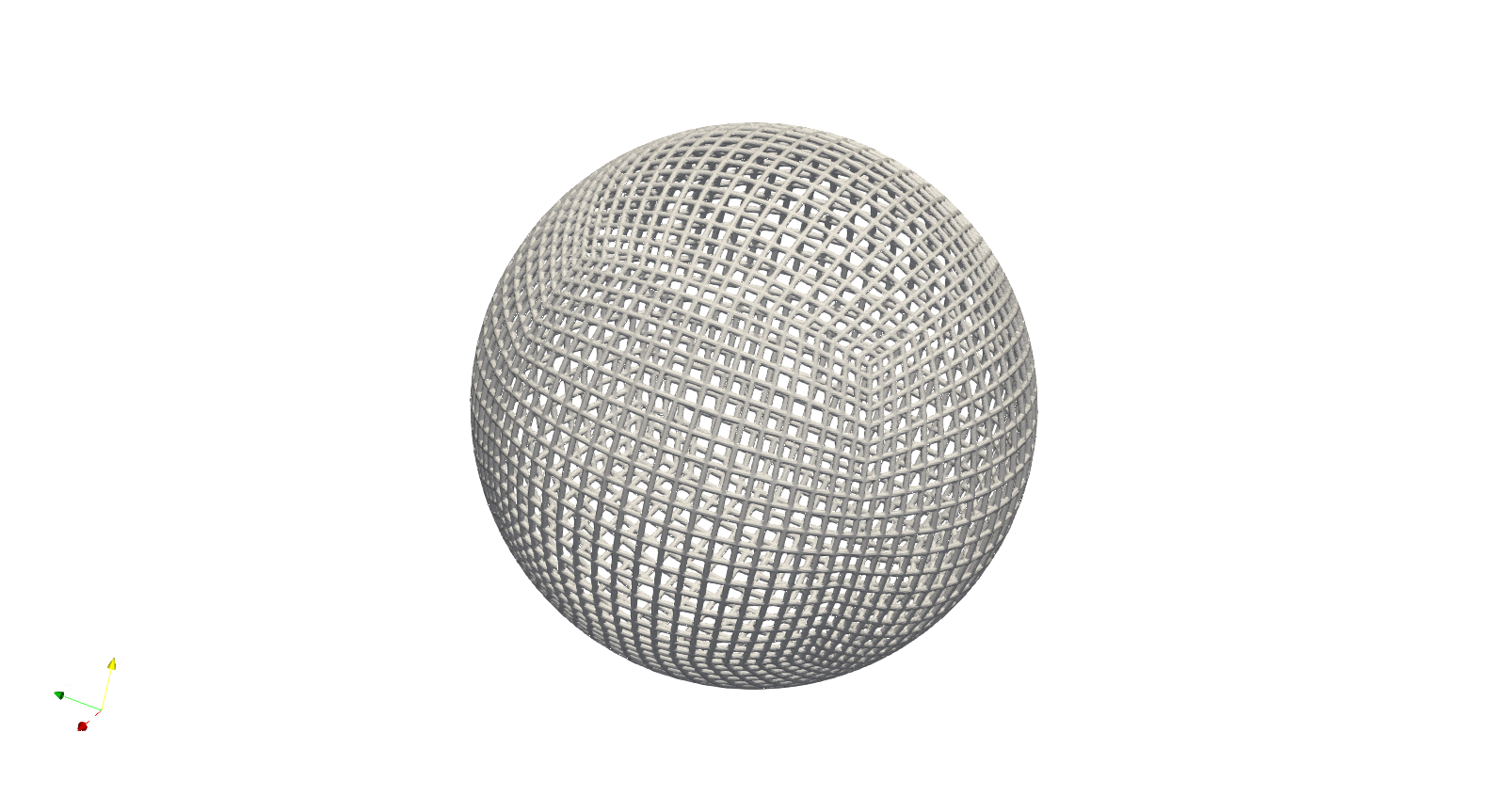
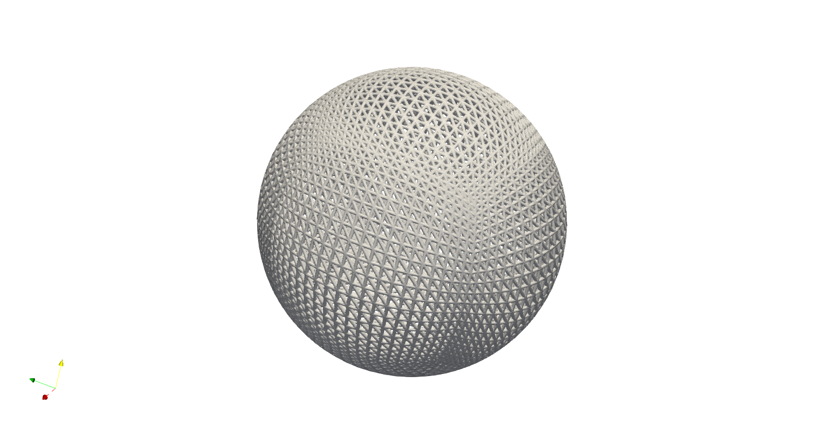
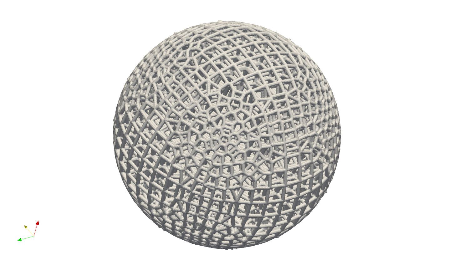
The surface mesher is a function based on the Cartesian mesher algorithm. It extracts the exterior element surfaces and projects the boundary nodes back onto the geometry’s surface. Similar to the Cartesian mesher, the surface mesher produces an approximated all-quad or quad-dominant mesh, which can be used to generate the surface lattice. Please note that the mesher only supports closed surface bodies. Here is a simple example of producing a quad element dominant mesh on a ball. Users can find this example in the file SurfaceLattice\Gen_BasicSurfQuadMesh.json.
{"Setup":{      "Type" : "Sample",
            "Sample": {"Domain" : [[-600.0, 600.0],[-600.0, 600.0],[-600.0, 600.0]], "Shape": "Box"},
            "Geomfile": "",
            "Rot" : [0.0,0.0,0.0],
            "res":[4.0, 4.0, 4.0],
            "Padding": 4,
            "onGPU": false,
            "memorylimit": 1073741824000
            },
"WorkFlow":{
      "1": {
           "Gen_BasicQuadMesh":{
             "num_elem": [20, 20, 20],
             "x_range": [0.0, 20.0],
             "y_range": [0.0, 20.0],
             "z_range": [0.0, 20.0],
             "ori":[-10.0,-10.0,-10.0],
             "Normal": [0.0,0.0,1.0],
             "z_angle": 0.0,
             "Meshfile": ".//Test_json//SurfaceLattice//BallSurfQuadMesh.med",
             "Geomfile": ".//sample-obj//Ball_Mesh.stl",
             "isProjection": true,
             "numCoverNodes": 1,
                     "isSplitTris": false
            }
           },
      "2": {"Add_Lattice":{
                "la_name": ".//Test_json//SurfaceLattice//BasicSurfQuadLattice.mld",
                "size": [15.0, 15.0, 15.0], "thk":7.0, "Rot":[0.0,0.0,0.0], "Trans":[0.0,0.0,0.0], "Inv": false, "Fill": false,
                "Cube_Request": {}
                }
           },
      "3":{
          "Export": {"outfile": ".//Test_results//BasicSurfMeshLattice.stl"}
          }

               },
"PostProcess":{"CombineMeshes": true,
            "RemovePartitionMeshFile": false,
            "RemoveIsolatedParts": true,
            "ExportLazPts": true}
}
Very similar to the keywords Gen_BasicCartesianHexMesh, the keywords Gen_BasicQuadMesh requires to setup the parameter of projection (isProjection) and number of covered nodes (numCoverNodes), moreover, it also asks whether splits a quad element as two triangle elements (isSplitTris). In this case, we do not want to split the quad element ("isSplitTris": false). The result mesh is below.
Or we could split the quad as two triangle by "isSplitTris": true.
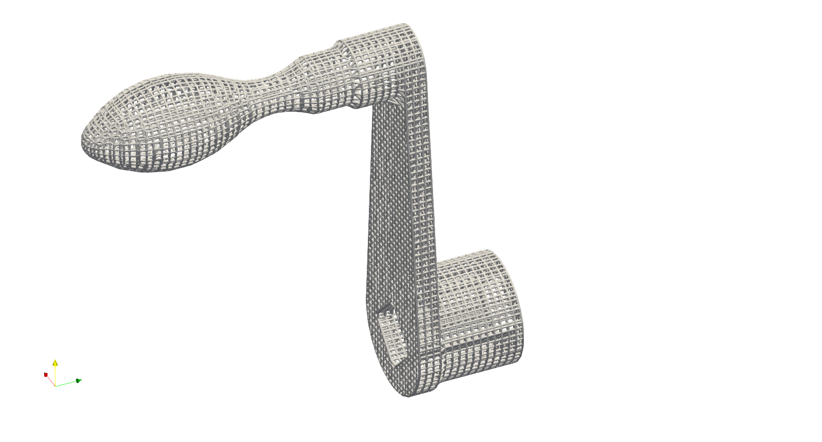
This function can certainly be applied to more complicated geometry. The provided example JSON can be located in the file named SurfaceLatticeGen_BasicSurfQuadMesh.json. This specific example illustrates the geometry of a crank handle, which is primarily composed of quadrilateral elements. It is important to note that while the majority of the elements in this mesh are quadrilaterals, some of these elements may exhibit significant distortion, resulting in shapes that closely resemble triangles. Despite this, the overall structure of the mesh predominantly consists of quadrilateral elements, making it a quad-dominant mesh.
The Gen_SimpleQuadMesh keyword offers an alternative approach for generating quadrilateral elements on a given mesh. The input mesh has to be a water tight closed mesh. The algorithm computes the cross-field of the input triangular mesh, which then guides the alignment of the quadrilateral elements. Users can refer to an example located at .//Test_json//SurfaceLattice//GenSimpleQuadMesh.json. This example demonstrates how to fill the exterior surface of a given mesh with quadrilateral elements.
{
     "Setup": {
         "Type": "Geometry",
         "Sample": {
             "Domain": [[0.0, 1.0], [0.0, 1.0], [0.0, 1.0]],
             "Shape": "Box"
         },
         "Geomfile": ".//sample-obj//shell_1_of_bdd_.stl",
         "Rot": [0.0, 0.0, 0.0],
         "res": [0.5, 0.5, 0.5],
         "Padding": 4,
         "onGPU": false,
         "memorylimit": 1073741824000
     },
     "WorkFlow": {
         "1": {
             "Gen_SimpleQuadMesh": {
                 "inp_meshfile": ".//sample-obj//shell_1_of_bdd_.stl",
                 "out_meshfile": ".//Test_results//Simple_quad.obj",
                 "size": [5.0, 5.0, 5.0]
             }
         },
         "2": {
             "Add_Lattice": {
                 "la_name": ".//Test_json//SurfaceLattice//SimpleQuadMesh.mld",
                 "size": [5.0, 5.0, 5.0],
                 "Rot": [0.0, 0.0, 0.0],
                 "Trans": [0.0, 0.0, 0.0],
                 "Inv": false,
                 "Fill": false,
                 "Cube_Request": {},
                 "thk": 1.0
             }
         },
         "10000": {
             "Export": {
                 "outfile": ".//Test_results//SimpleQuadMesh.stl"
             }
         }
     },
     "PostProcess": {
         "CombineMeshes": true,
         "RemovePartitionMeshFile": false,
         "RemoveIsolatedParts": true,
         "ExportLazPts": false
     }
}
Parameter |
Details |
|---|---|
|
a string showing the path and file name of the input mesh. |
|
a string showing the path and file name of the output mesh. |
|
a list contains three float numbers. The algorithm only takes the first and second elements, and the generated quadrilateral elements approximated the defined size. |
Voronoi Polygon#
A Voronoi diagram, also known as a Voronoi tessellation or Voronoi decomposition, is a geometric structure that partitions a space into regions based on the proximity to a set of given points. In a Voronoi diagram, each point in the set is associated with a unique region that consists of all locations in the space that are closer to that point than any other point. It is named after the Russian mathematician Georgy Voronoi, who first introduced the idea. Voronoi polygons have various applications, such as in computer graphics, spatial analysis, geographical information systems, and computational biology. They provide a way to partition space based on proximity and are useful in solving proximity-based problems and analyzing spatial patterns. In additive manufacturing, this structure is often used on the components which suppose to bear loading with cushioning effect.
Setup the generation of the Voronoi polygons on the given geometry is similar to the tet mesher. Below shows the piece of setup JSON (the file GenVorMesh.json).
{"Setup":{  "Type" : "Geometry",
            "Geomfile": ".//sample-obj//Ball_Mesh.STL",
            "Rot" : [0.0,0.0,0.0],
            "res":[5.0,5.0,5.0],
                    "Padding": 4,
            "onGPU": false,
            "memorylimit": 16106127360
            },
 "WorkFlow":{
      "1": {"Gen_VoronoiPolyMesh":{
                "Geomfile": ".//sample-obj//Ball_Mesh.STL",
                        "size": [100.0,100.0,100.0],
                        "Meshfile": ".//sample-obj//Ball_VorMesh.med",
                        "remove_tol": 5.0
                }
           },
      "2": {"Add_Lattice":{
                "la_name": ".//Test_json//MeshLattice//GenVorMesh.mld",
                "size": [150.0,150.0,150.0], "thk":10.0, "Rot":[0.0,0.0,0.0], "Trans":[0.0,0.0,0.0], "Inv": false, "Fill": false,
                "Cube_Request": {}
                }
           },
      "3":{
          "Export": {"outfile": ".//Test_results/BallBasicVoriMesh_Lattice.stl"}
          }
               },
 "PostProcess":{
            "CombineMeshes": true,
            "RemovePartitionMeshFile": false,
            "RemoveIsolatedParts": true,
            "ExportLazPts": true
            }
}
The parameter setup is very similar to the keywords Gen_TetBasicMesh. The additional parameter remove_tol defines tolerance of removing the strut which contains the end node outside of the given geometry. The mesh is an approximation of geometry, sometime, the end-nodes may locate beyond the boundary of geometric shape. This parameter allows user to flexibly remove such. The results are shown below.

And the cross-section view shows how the mesher generates the element layer by layer.

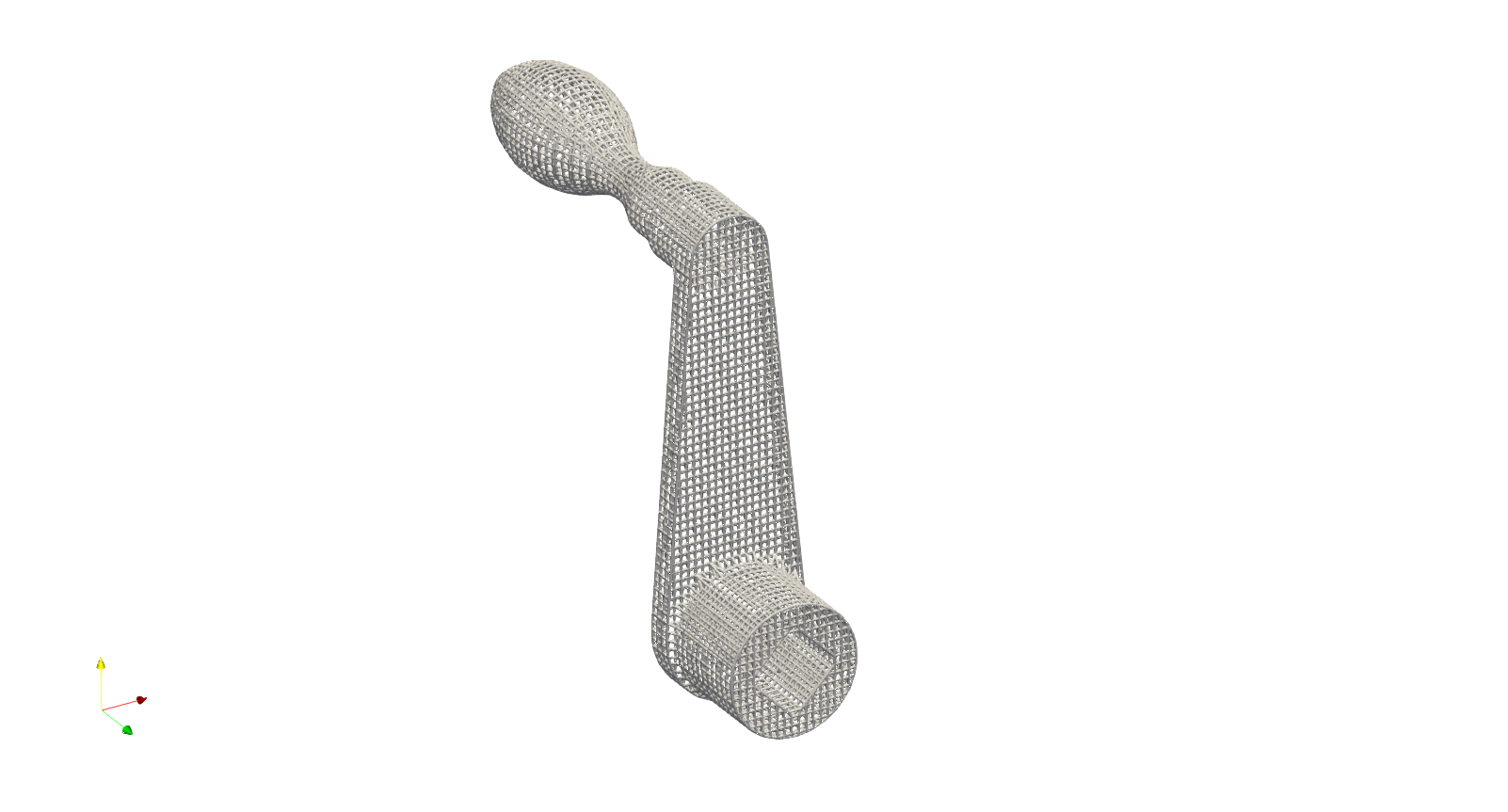
We can certainly apply this to a more complex geometry. The example below (GenVorMesh_crank_handle.json) shows the generation of the Voronoi polygons on a real world component.
{"Setup":{  "Type" : "Geometry",
            "Geomfile": ".//sample-obj//crank_handle.stl",
            "Rot" : [0.0,0.0,0.0],
            "res":[0.25,0.25,0.25],
                  "Padding": 4,
            "onGPU": false,
            "memorylimit": 16106127360000000
            },
 "WorkFlow":{
      "1": {"Gen_VoronoiPolyMesh":{
                "Geomfile": ".//sample-obj//crank_handle.stl",
                        "size": [3.0,3.0,3.0],
                        "Meshfile": ".//sample-obj//crank_handle.med",
                        "remove_tol": 0.6
                }
           },
       "2": {"Add_Lattice":{
                "la_name": ".//Test_json//MeshLattice//GenVorMesh_crank_handle.mld",
                "size": [3.5,3.5,3.5], "thk":0.5, "Rot":[0.0,0.0,0.0], "Trans":[0.0,0.0,0.0], "Inv": false, "Fill": false,
                "Cube_Request": {}
                }
           },
       "3":{
            "Export": {"outfile": ".//Test_results/crank_handle_VoriMesh_Lattice.stl"}
          }
                },
 "PostProcess":{"CombineMeshes": true,
            "RemovePartitionMeshFile": false,
            "RemoveIsolatedParts": true,
            "ExportLazPts": true}
}
And the mesh lattice defintion (GenVorMesh_crank_handle.mld) is:
{
    "type": "MeshLattice",
    "definition": {
        "meshfile": ".//sample-obj//crank_handle.med"
    }
}
The result is shown as below. As mentioned before, the current mesh strategy may not handle the sharp edge very well, but, in general, it produces a good fitting of Voronoi polygons.

Similar to the tetrahedron mesher, Artisan also features a Voronoi mesher that utilizes the vertices of the Cartesian mesh. The example file GenVorMesh_HexSplit.json includes the keyword Gen_VoronoiPolyMesh, which generates a partial Voronoi mesh using the vertices of the Cartesian mesh.
Surface Remesh#
The function utilizes the Artisan infrastructure of extracting the mesh from field. Often user may load a geometry and re-export it out for remeshing the surface triangles. The keyword Gen_SurfaceReMesh does the combined functions. User may find the example of Engine bracket remeshing at Remesh\EngineBracket_Infill_LR.json.
{"Setup":{ "Type" : "Geometry",
           "Geomfile": ".//sample-obj/EngineBracket.stl",
           "Rot" : [0.0,0.0,0.0],
           "res":[0.4,0.4,0.4],
                 "Padding": 1,
           "onGPU": false,
           "memorylimit": 16106127360
           },
"WorkFlow":{
   "1": {"Gen_SurfaceReMesh":{
         "size":[3.0, 3.0, 3.0],
         "mesh_file":".//sample-obj//EngineBracket.stl",
         "ShortEdgeThreshold": 1.0,
         "export_mesh": ".//Test_json//MeshLattice//Remesh//EngineBracket_Remesh.stl"}
        },

   "2": {"Add_Lattice":{
           "la_name": ".//Test_json//MeshLattice//Remesh//EngineBracket.mld",
           "size": [3.5, 3.5, 3.5], "thk":0.5, "Rot":[0.0,0.0,0.0], "Trans":[0.0,0.0,0.0], "Inv": false, "Fill": false,
           "Cube_Request": {}
           }
      },
   "3":{
     "Export": {"outfile": ".//Test_results/EngineBracket_Remesh_MeshLattice.stl"}
     }

      },
"PostProcess":{"CombineMeshes": true,
           "RemovePartitionMeshFile": false,
           "RemoveIsolatedParts": true,
           "ExportLazPts": false}
}
The keyword Gen_SurfaceReMesh has the following parameters definitions.
Parameter |
Details |
|---|---|
|
the average size of the mesh; |
|
read in mesh file, if none, i.e. |
|
the threshold of short edge, any edges shorter than this shall be collapsed; |
|
the resultant mesh |
Please note, this is not the universal remesher, but a simple remeshing function for a mesh with averaging size.
The input mesh geometry may contain sharp or non-smooth features. To improve surface quality, the mesh can be smoothed and remeshed using the keyword Proc_Mesh_Smoothing. This process is controlled by the following parameters:
Parameter |
Details |
|---|---|
|
The input watertight triangular surface mesh. |
|
The output triangular surface mesh after smoothing. |
|
The characteristic size of geometric features to be smoothed. Smaller features below this size will be removed during smoothing. |
Stacked Layer Mesher#
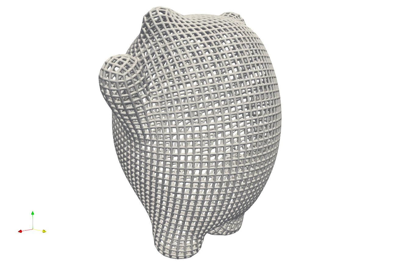
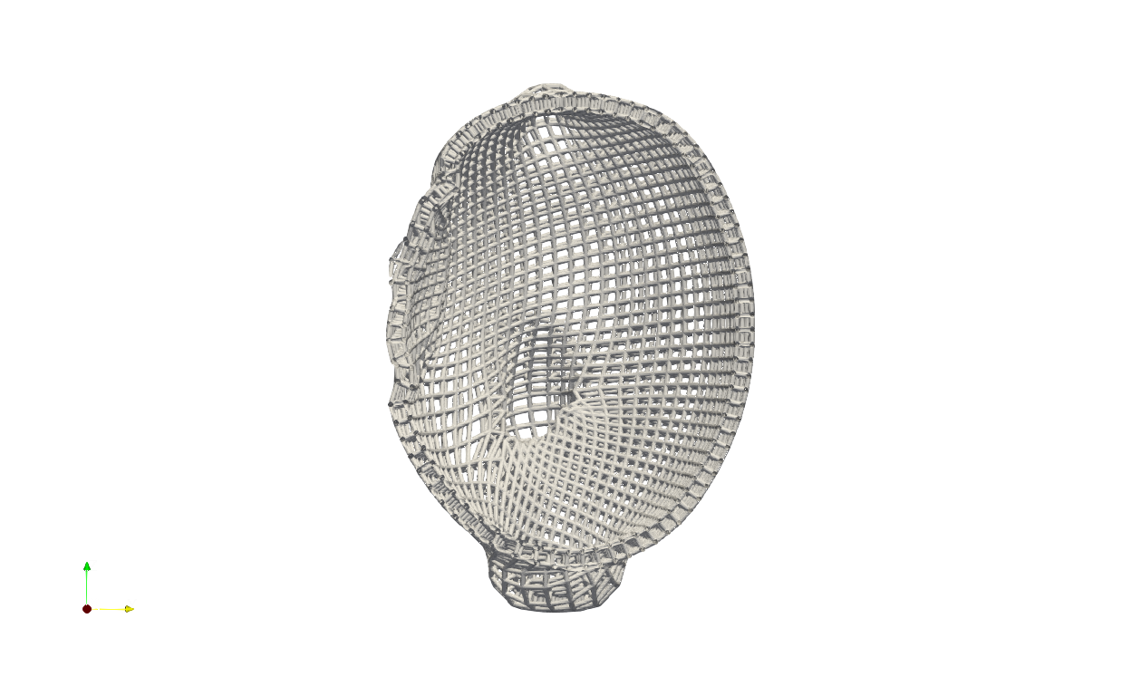
The stacked-layer mesher offers a simple way to generate a conformal mesh around a geometry’s exterior surface by adding successive layers of hexahedral elements in the normal direction. The example .\Test_json\StackedLayerLattice\GenStackedLayerLattice.json` demonstrates a simple workflow that combines the quad surface mesher with the stacked-layer mesher to generate a hexahedral mesh on the exterior surface.
{
  "Setup": {
      "Type": "Geometry",
      "Sample": {
          "Domain": [
              [
                  0.0,
                  1.0
              ],
              [
                  0.0,
                  1.0
              ],
              [
                  0.0,
                  1.0
              ]
          ],
          "Shape": "Box"
      },
      "Geomfile": ".//sample-obj//shell_1_of_bdd_.stl",
      "Rot": [
          0.0,
          0.0,
          0.0
      ],
      "res": [
          0.5,
          0.5,
          0.5
      ],
      "Padding": 10,
      "onGPU": false,
      "memorylimit": 1073741824000
  },
  "WorkFlow": {
      "1": {
          "Gen_SimpleQuadMesh": {
              "inp_meshfile": ".//sample-obj//shell_1_of_bdd_.stl",
              "out_meshfile": "simple_quad",
              "size": [
                  5.0,
                  5.0,
                  5.0
              ]
          }
      },
      "2":{
          "Gen_StackedLayerMesh":{
              "inp_meshfile":"simple_quad",
              "inp_geommeshfile": ".//sample-obj//shell_1_of_bdd_.stl",
              "out_meshfile": "stacked_layer_mesh",
              "num_layers":1,
              "layer_thk": 6.0,
              "projection_direction": 1
          }
      },
      "3": {
          "Add_Lattice": {
              "la_name": ".//Test_json//StackedLayerLattice//StackedLayerMesh.mld",
              "size": [
                  7.0,
                  7.0,
                  7.0
              ],
              "Rot": [
                  0.0,
                  0.0,
                  0.0
              ],
              "Trans": [
                  0.0,
                  0.0,
                  0.0
              ],
              "Inv": false,
              "Fill": false,
              "Cube_Request": {},
              "thk": 1.0
          }
      },
      "10000": {
          "Export": {
              "outfile": ".//Test_results//SimpleStackedLayerMesh.stl"
          }
      }
  },
  "PostProcess": {
      "CombineMeshes": true,
      "RemovePartitionMeshFile": false,
      "RemoveIsolatedParts": true,
      "ExportLazPts": false
  }
}
In above workflow, the keyword Gen_StackedLayerMesh generates a single layer of hex mesh using the surface quad mesh generated by Gen_SimpleQuadMesh. This layer of hex mesh naturally conforms the shape of the given geometry. The parameters of Gen_StackedLayerMesh are explained below.
Parameter |
Details |
|---|---|
|
input surface quad mesh file, or mesh id. |
|
the geometry file or mesh id for generating conformal stacked layer mesh. |
|
the resultant mesh id, or a string file path. |
|
the number of stacked layers. |
|
A negative value indicates projection inward, and a positive value indicates projection outward. |
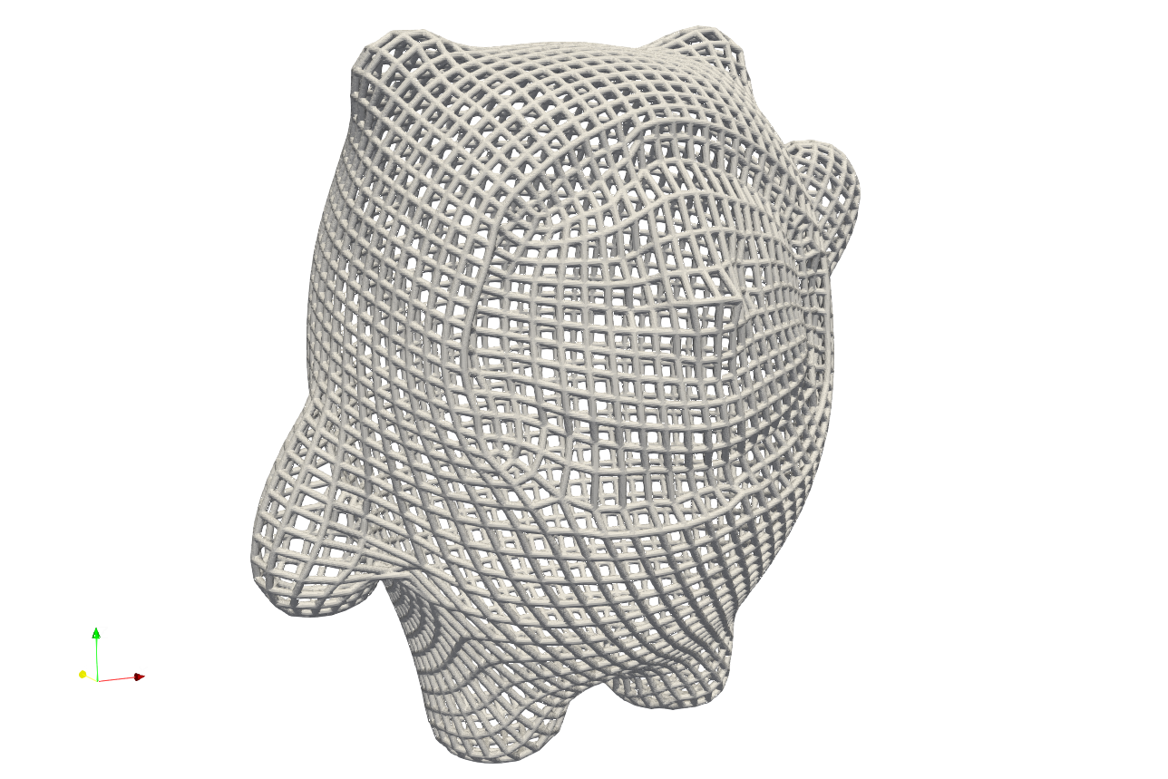
The resultant mesh lattice are presented below. Same as other mesh, uSer may use this mesh to fill with other type of lattice as well.
Contour Lines#
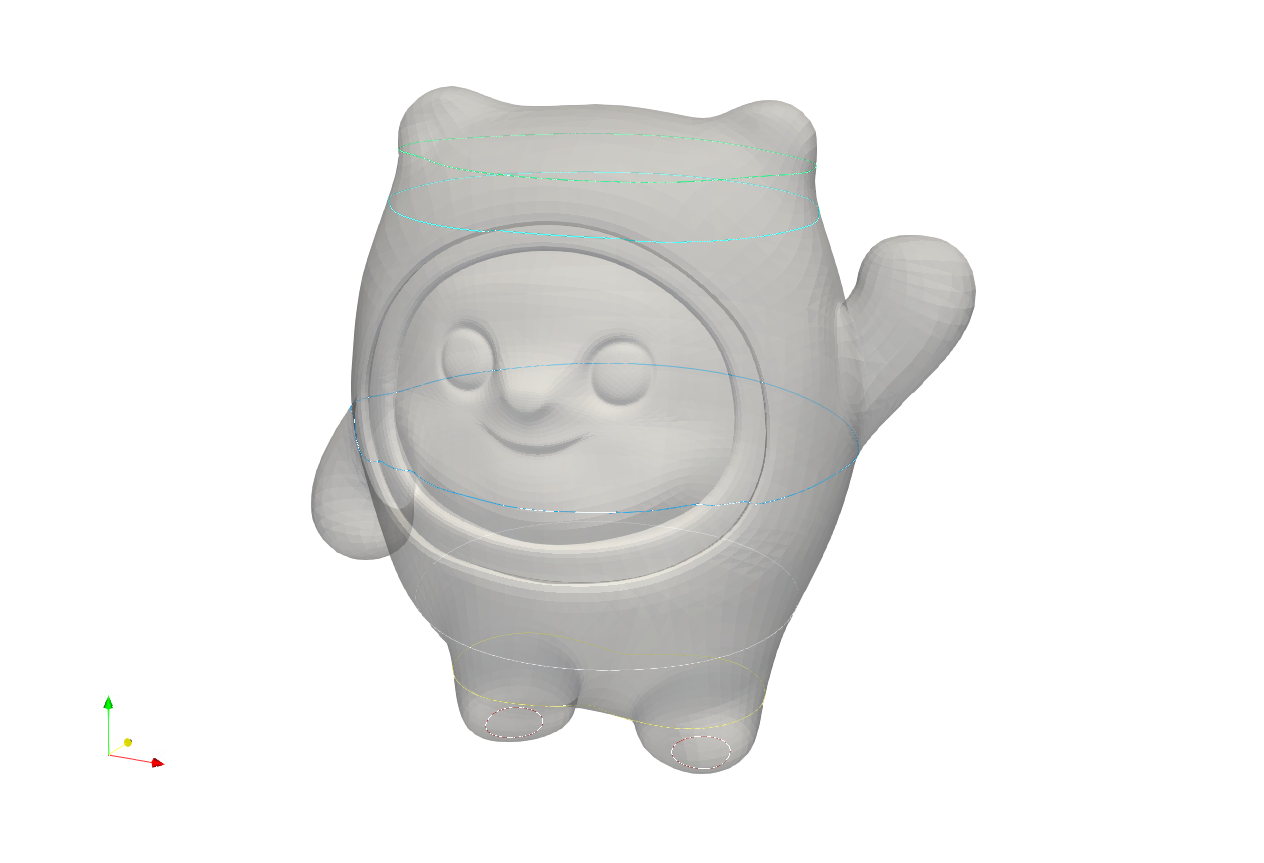
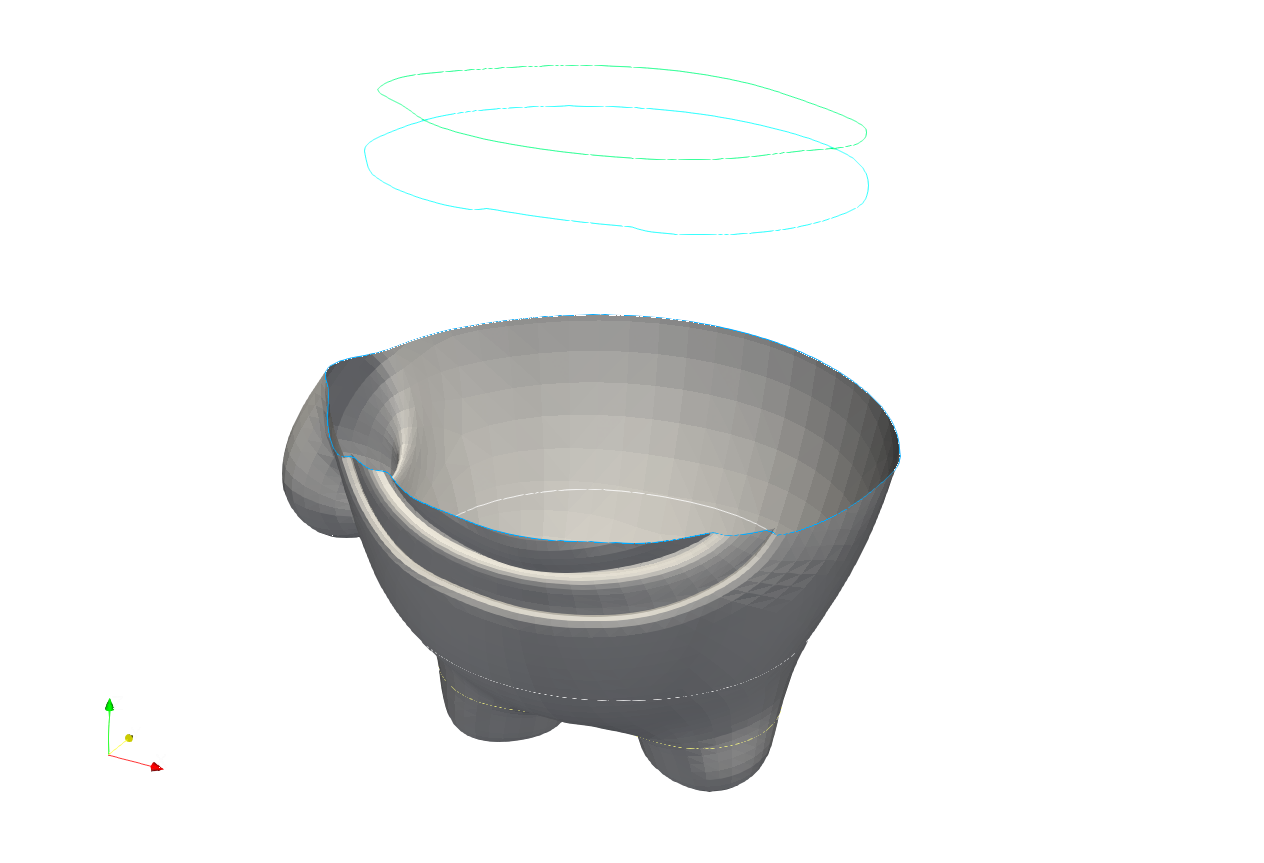
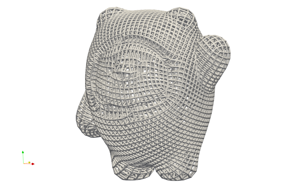
Artisan can generate contour lines for any given geometry. These lines can be exported as a line mesh, allowing users to generate reinforcement patterns on a model’s exterior or develop custom slicing algorithms for 3D printing. An example of this process can be found in .//Test_json//ContourLines//Test_BingDunDun.json
 {
   "Setup": {
       "Type": "Geometry",
       "Sample": {
           "Domain": [
               [0.0, 0.0],
               [0.0, 0.0],
               [0.0, 0.0]
           ],
           "Shape": "Box"
       },
       "Geomfile": ".//sample-obj//shell_1_of_bdd_.stl",
       "Rot": [0.0, 0.0, 0.0],
       "res": [1.0, 1.0, 1.0],
       "Padding": 1,
       "onGPU": false,
       "JsonWorkDir": false,
       "memorylimit": 161061273000
   },
   "WorkFlow": {
       "1": {
           "Add_Geometry":{
                  "Name": ".//sample-obj//shell_1_of_bdd_.stl",
                  "k_factor": 0.0,
                  "push2GeomField": false,
                  "Paras": {
                      "Scale": [1.0, 1.0, 1.0],
                      "Trans": [0.0, 0.0, 0.0],
                      "Rot": [0, 0, 0]
                     }
                 }
       },
       "2": {
           "Gen_Z_ContourLines":{
               "res": [1.2, 1.2, 1.2],
               "PlaneHeights": [0, 20, 50, 100, 165, 178],
               "out_meshfile": ".//Test_results//contourlines_BingDunDun.contour"
           }

       }
   },
   "PostProcess": {
       "CombineMeshes": true,
       "RemovePartitionMeshFile": false,
       "RemoveIsolatedParts": true,
       "ExportLazPts": false
   }
}
This JSON file generates contour lines at heights of 0, 20, 50, 100, 165, and 178. The system first reads the geometry into the lattice field, then utilizes the Gen_Z_ContourLines keyword to produce the lines at the specified elevations. Gen_Z_ContourLines generates the contour lines along Z direction. The parameters for the Gen_Z_ContourLines keyword are defined below:
Parameter |
Details |
|---|---|
|
a list of three float numbers represnets the mesh resolution in X, Y and Z direction. |
|
a list of float numbers defines the slicing height for generating the contours. |
|
the resultant mesh file. It has two exported formats, the mesh format, e.g. |
Below shows the comparsion between the original model and contour lines.