Field Driven Meshing#
Fields can serve as design parameters for mesh generation in Artisan. Within this framework, fields can be applied to either modify local material thickness or adjust the size of lattice units.
Scaler Field#
The variation in unit cell size can be achieved using specific keywords: Gen_BasicCartesianHexMesh_MultiSize and Gen_TetBasicMesh_HexSplit. The former keyword allows for the creation of hex elements with varying sizes, while the latter facilitates the generation of tet elements with varying sizes. User shall find all examples below at .\Test_json\MeshLattice\Box_FieldAttractor_MultiSize.
Similar to previously demonstrated applications, users can activate a specific function in Artisan by setting the parameter "Type": "Field_Attractor". This configuration prompts Artisan to import a field, represented as a spatial data cloud containing field values. This potential map are utilized to create an attraction field. This field influences the mesh nodes, driving their deformation. As a result, this process generates elements of varying sizes throughout the mesh. This functionality allows for the tailored manipulation of mesh structures to align with specific design criteria or performance requirements, for example, user may use stress or strain mapping as design parameters to drive the local element size.
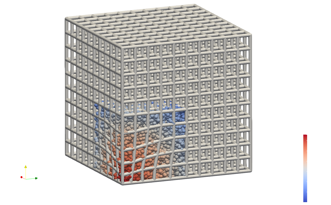
The example in the file Box_FA_MS.json demonstrates how the local field changes a box mesh element size, as shown below.
{
"Setup": {
    "Type": "Sample",
    "Sample": {
        "Domain": [
            [0.0, 80.0],
            [0.0, 80.0],
            [0.0, 80.0]
        ],
        "Shape": "Box"
    },
    "Geomfile": "",
    "Rot": [ 0.0, 0.0, 0.0],
    "res": [ 0.25, 0.25, 0.25],
    "Padding": 4,
    "onGPU": false,
    "memorylimit": 1073741824000
},
"WorkFlow": {
    "1": {
        "Gen_BasicCartesianHexMesh_MultiSize": {
            "num_elem": [
                10,
                10,
                10
            ],
            "x_range": [
                0.0,
                80.0
            ],
            "y_range": [
                0.0,
                80.0
            ],
            "z_range": [
                0.0,
                80.0
            ],
            "ori": [
                0.0,
                0.0,
                0.0
            ],
            "Normal": [
                0.0,
                0.0,
                1.0
            ],
            "z_angle": 0.0,
            "Meshfile": ".//Test_json//MeshLattice//Box_FieldAttractor_MultiSize//BoxHexMesh.med",
            "Geomfile": ".//sample-obj//cube_1mm.stl",
            "numPrjLayers": 0,
            "LayerDepth": 1.0,
            "numCoverNodes": 0,
            "MultiSize": {
                "Type": "Field_Attractor",
                "Data": [
                    [
                        30,
                        0.5
                    ]
                ],
                "FieldFile": ".//Test_json//MeshLattice//Box_FieldAttractor_MultiSize//field_data.csv"
            }
        }
    },
    "2": {
        "Add_Lattice": {
            "la_name": ".//Test_json//MeshLattice//Box_FieldAttractor_MultiSize//GenHexMesh.mld",
            "size": [
                5.0,
                5.0,
                5.0
            ],
            "thk": 1.0,
            "Rot": [
                0.0,
                0.0,
                0.0
            ],
            "Trans": [
                0.0,
                0.0,
                0.0
            ],
            "Inv": false,
            "Fill": false,
            "Cube_Request": {}
        }
    },
    "3": {
        "Export": {
            "outfile": ".//Test_results/BoxHexMesh_FieldAttractor_MultiSize.stl"
        }
    }
},
"PostProcess": {
    "CombineMeshes": true,
    "RemovePartitionMeshFile": false,
    "RemoveIsolatedParts": true,
    "ExportLazPts": false
}
}
Here the parameter MultiSize contains three setup parameters:
Parameter |
Details |
|---|---|
|
supports |
|
when |
|
This defines the field file path, i.e. csv file. The field file shall contains the x, y, z and field value. Use shall refer to Field Operation for file format details. |
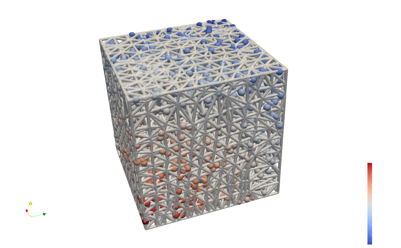
In the example, the csv file contains many spatial data points, this could lead longer computational time. The example Box_FA_tetmesh_MS.json demonstrates the operations on the tet mesh. The section that defines the field operation is as below.
"1": {
        "Gen_TetBasicMesh_HexSplit": {
            "Geomfile": ".//sample-obj//cube_1mm.stl",
            "size": [
                100.0,
                100.0,
                100.0
            ],
            "Meshfile": ".//Test_json//MeshLattice//Box_FieldAttractor_MultiSize//BoxHexMesh.med",
            "ConvertTet2Beam": false,
            "MultiSize": {
                "Type": "Field_Attractor",
                "Data": [
                    [
                        30,
                        0.5
                    ]
                ],
                "FieldFile": ".//Test_json//MeshLattice//Box_FieldAttractor_MultiSize//tetmesh_field_data.csv"
            }
        }
    },
The results is below. Please note that two examples here used different domain size and fields. The field can be either full coverage on the domain, or partially covers the interested areas. It is highly recommend to place more spatial points on the high interested area in order to interpolate the field values at the nodal positions.
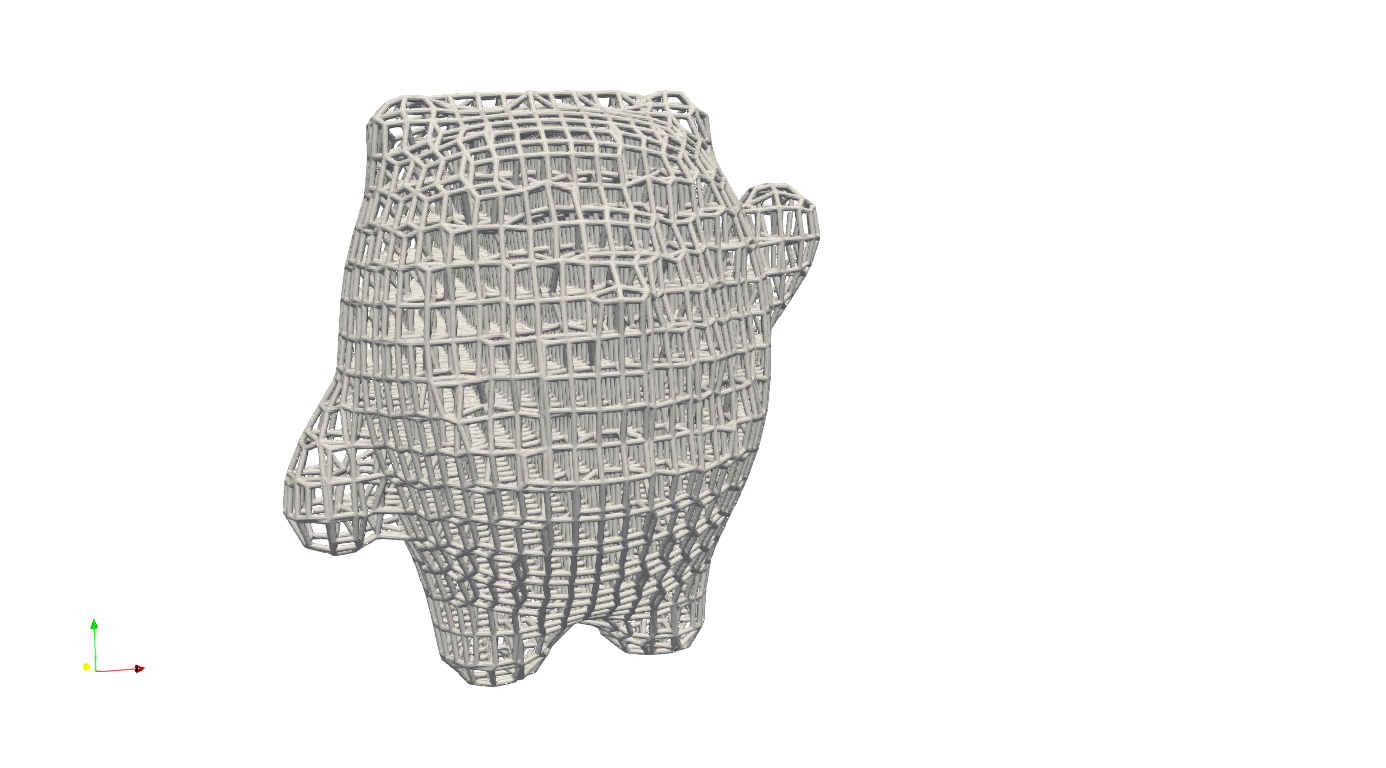
Geometry Field#
The geometric distance field can be served as the design parameter that varies the local mesh size. The keyword Gen_ExtHexMesh_Geomfield provides a simple interface that reads the external mesh, projects the exterior nodes on the given geometry’s exterior surface, and then use geometric distance field adjust the interior nodes position. The example .//Test_json//MeshLattice//ExtMesh//Mesh_GeomField.json shows how to read the external mesh (generated using Gen_BoxMesh) and fill a geometry.
    {
    "Setup": {
        "Type": "Geometry",
        "Sample": {
            "Domain": [
                [
                    0.0,
                    1.0
                ],
                [
                    0.0,
                    1.0
                ],
                [
                    0.0,
                    1.0
                ]
            ],
            "Shape": "Box"
        },
        "Geomfile": "C:/Users/wangy/Documents/Project-Artisan/Artisan/Artisan/Src/sample-obj/shell_1_of_bdd_.stl",
        "Rot": [
            0.0,
            0.0,
            0.0
        ],
        "res": [
            0.5,
            0.5,
            0.5
        ],
        "Padding": 4,
        "onGPU": false,
        "memorylimit": 1073741824000
    },
    "WorkFlow": {
        "1": {
            "Gen_BoxMesh": {
                "Normal": [
                    0.0,
                    0.0,
                    1.0
                ],
                "z_angle": 0.0,
                "Mesh_file": ".//Test_json//MeshLattice//ExtMesh//Base_Mesh.med",
                "y_range": [
                    0.0,
                    140.0
                ],
                "z_range": [
                    0.0,
                    200.0
                ],
                "ori": [
                    -190.0,
                    -68.0,
                    -2.0
                ],
                "x_range": [
                    0.0,
                    200.0
                ],
                "num_elem": [
                    25,
                    18,
                    18
                ]
            }
        },
        "2": {
            "Gen_ExtHexMesh_Geomfield": {
                "Geomfile": "",
                "out_meshfile": ".//Test_json//MeshLattice//ExtMesh//Base_Mesh_Field.med",
                "isPreAttraction": false,
                "inp_meshfile": ".//Test_json//MeshLattice//ExtMesh//Base_Mesh.med",
                "numCoverNodes": 4,
                "AttractionRatio": 0.1
            }
        },
        "3": {
            "Add_Lattice": {
                "thk": 1.0,
                "Rot": [
                    0.0,
                    0.0,
                    0.0
                ],
                "Trans": [
                    0.0,
                    0.0,
                    0.0
                ],
                "Inv": false,
                "Fill": false,
                "Cube_Request": {},
                "la_name": ".//Test_json//MeshLattice//ExtMesh//Bdd_MeshLattice.mld",
                "size": [
                    13.0,
                    13.0,
                    13.0
                ]
            }
        },
        "10000": {
            "Export": {
                "outfile": ".//Test_results//ExMesh_Geomfield.stl"
            }
        }
    },
    "PostProcess": {
        "CombineMeshes": true,
        "RemovePartitionMeshFile": false,
        "RemoveIsolatedParts": true,
        "ExportLazPts": false
    }
}
The keywords Gen_ExtHexMesh_Geomfield parameters are listed below.
Parameter |
Details |
|---|---|
|
the geometry file path, if empty, it will take the geometry defined in setup; |
|
resultant mesh file; |
|
the read-in external mesh file; |
|
the read-in mesh will check the coverage by using number of nodes, the elements having less number of nodes covered will be removed. |
|
If true, the mesh nodes would adjust using the geometric distance field, if false, the interior nodes will be adjusted after the elements removal. |
|
the multiple scale to the nodal movement magnitude, if 0, field effect will not be applied. |
Above case generates the following infill. In practices, use may consider use other professional mesher to forms a general approximated mesh, and then use this keyword to refine the boundary projection, and the interior nodes positions.