Inspect models in the 3D Workspace#
The viewer loads meshes, Artisan HDF5 fields and CSV/TSV point clouds for inspection. Camera, display, section and measurement controls do not change the workflow geometry or the mesh on disk. After changing workflow parameters, generate and reload a result to see the new design.
Move around the model#
Use Orbit, Pan or Zoom in the navigation selector to assign that action to the left mouse button. The middle button zooms. More → Mouse controls contains right-button preferences, sensitivity and reverse-scroll zoom. Touch navigation uses one finger to orbit and two to pan/zoom.
Choose Fit view to frame the visible layers or Reset for an isometric camera. The View selector provides front, back, left, right, top, bottom and isometric views. You can also click a face, edge or corner of the orientation cube. Z is the vertical axis.
Switch between Perspective and Orthographic projection as needed. The display selector offers Solid, Wireframe and Solid + edges. Dense triangle edges may obscure small features; return to Solid for a clear surface view.
Compare source and result#
Load source updates the workflow source; Load result adds a result layer. Use Geometry → + Add for other reference meshes. All layers retain their original coordinate positions so aligned inputs and outputs can be compared.
Open Visibility to show or hide layers and change their colour and opacity. Use Make active to choose the layer affected by the preview-detail switch. For a lattice infill, hide the solid source first; otherwise it may cover the structure you are trying to inspect.
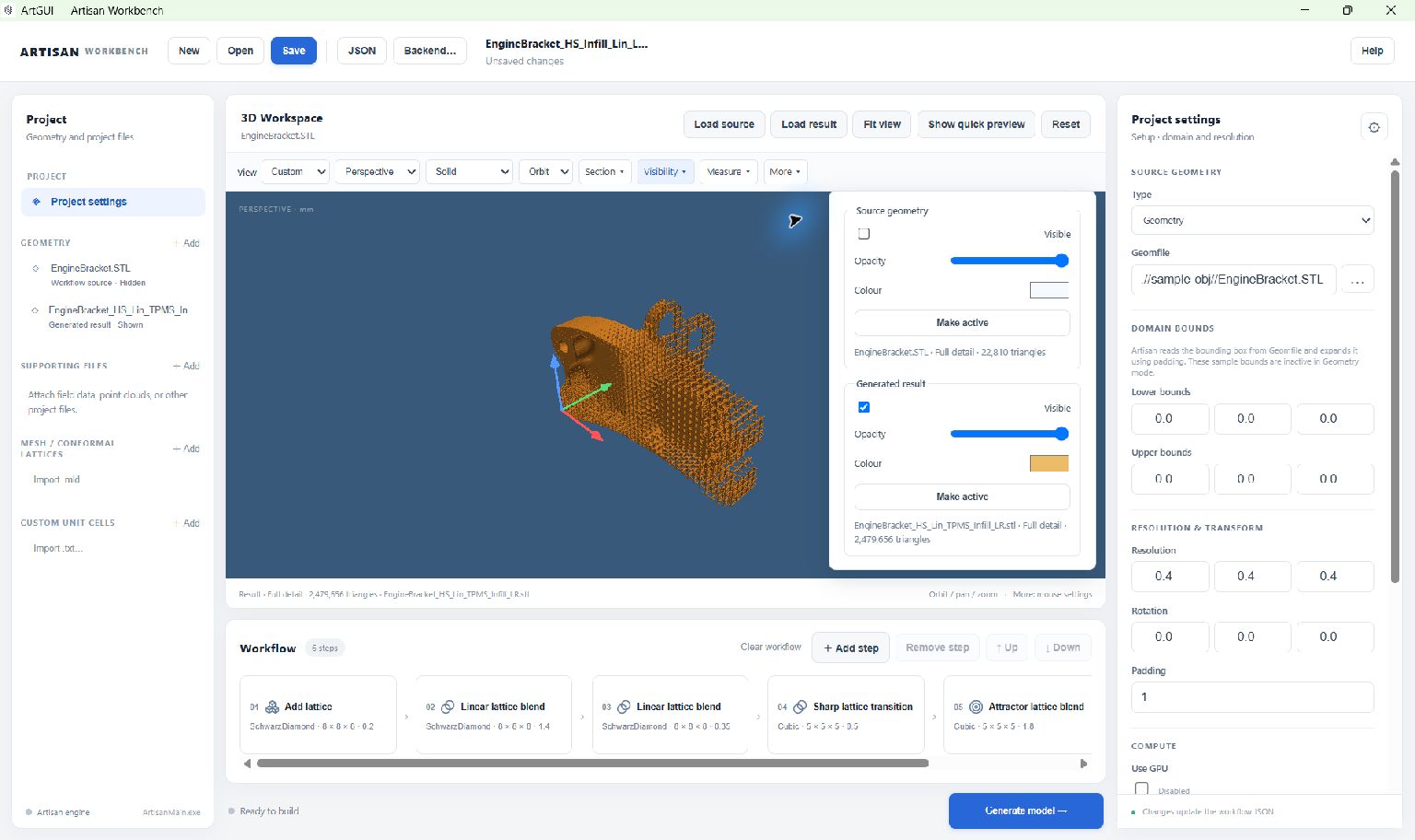
Hide the source to inspect an infill result. Each layer has independent visibility, opacity and colour controls.#
Transparency is useful for an overlay, but complex intersecting surfaces can show sorting artefacts. Inspect each layer separately if an overlap is unclear.
Independent colour and opacity controls#
Select the object in the Project tree, then use its Properties panel:
Geometry: use Display → Display colour and Display → Opacity. Source, reference and result geometries each have their own settings. A supported mesh in Supporting files has its own opacity too.
Field: use Display → Field opacity in the Field inspector. Each field file and field ID retains its own opacity. Changing to another field does not apply the first field’s setting to it.
Point cloud: use Point opacity in the selected cloud’s Properties. This changes the points, including their transparency when overlaid on a model; it does not dim the geometry.
The selected Properties panel contains only that object’s opacity control. Opening, editing or removing a field or point cloud leaves other objects’ opacity and visibility unchanged. To dim a mesh behind a field or points, select that mesh and change its own Opacity. The Visibility menu’s geometry opacity controls edit the same settings as geometry Properties.
Opacity 0 makes the object transparent and 1 (100%) makes it opaque. Choose Save or Save as to retain geometry colours and per-object opacity in the project JSON. Geometry settings survive preview/full-detail reloads; point settings survive reopening the saved reference. These display changes do not modify model coordinates, field values or source files.
Adaptive Preview and Full Detail#
Preview follows zoom, pan and orbit, showing more detail near the area you are inspecting and less elsewhere. It supports STL, OBJ, ASCII PLY and the supported flat INP meshes. Read the viewport footer to check which layer and detail mode are active. Allow new detail to finish loading after moving the camera.
The first opening prepares reusable display data on disk. It can take time and disk space for a large model; progress can be cancelled. Later openings reuse the completed cache. Changing the source file requires updated preview data. The original mesh and workflow are unchanged.
Select a layer in Project, or use Make active in Visibility, then choose Load full detail when you need the complete mesh. ArtGUI retains the previous preview until the new load succeeds. Use Cancel beside the progress indicator to stop loading. Show quick preview returns to Preview.
Important
Preview is an approximate display, not a simplified export or a replacement for the original mesh. Measurements require a visible Full Detail mesh. Use Full Detail before deciding that a surface has holes or missing parts.
Full-detail capacity depends on current RAM, graphics and viewer resources. STL loading checks memory during loading. If it pauses, Continue in preview keeps the existing preview; Continue loading resumes with checks still active. For other supported mesh formats, a resource warning can offer Continue in preview or Load full geometry. Attempting a full load despite a warning can exhaust resources; it is not a promise that it will fit. Close unused layers and use Preview when full detail cannot complete.
Clean temporary preview files#
Preview data is stored in ViewScratch beside ArtGUI.exe, independently
of the project folder. Keep the application in a writable folder with enough
free space. Completed caches from the previous application-cache location
are moved there when their models are opened.
Choose Clean scratch, beside Reset in the 3D Workspace header, to delete all files and subfolders inside ViewScratch. The ViewScratch folder itself remains. Active preview work is cancelled and cached preview layers are closed before their files are deleted. Reopen an affected geometry from Project or use Preview mesh to prepare its preview again.
Use ViewScratch only for temporary preview data: everything inside it is deleted. Project JSON, source models and exported results stored outside that folder are kept. Loaded Full Detail meshes, fields and point clouds remain displayed. If cleanup reports a file in use, close other ArtGUI windows using the cache and retry. Reset only changes the camera; it does not clean scratch files.
Look inside with a section plane#
Open Section and enable the section display.
Choose X, Y or Z, or enter a custom plane normal.
Move the position slider through the model.
Reverse the visible side if needed. Disable the section to restore the complete view.
This clips the display only. It does not create a capped cross-section, modify the STL, or export a cut model. On solid INP meshes, it clips the visible outer boundary; it does not reveal every internal element face.
Measure a distance or angle#
Load Full Detail for the model you want to measure and make it visible.
Open Measure, choose that model, and select Distance — 2 points or Angle — 3 points.
Click two points for a distance. For an angle, click three points with the vertex as the second point.
Enable Snap to triangle vertices when you want measurements based on nearby mesh vertices. INP beam measurements can snap to endpoints.
Return the measurement tool to Off when finished.
Measurements describe the loaded mesh and its floating-point precision. They do not measure the underlying implicit field or an exact CAD surface. Picking may be slower on very large meshes. Annotations are session-only and are cleared when their model is replaced.
Note
Mesh coordinates do not carry a guaranteed unit system. More → Unit label changes the displayed label, not the model scale. If the file was created in millimetres, use mm; selecting inches does not convert it.
Save a view or an image#
More contains grid, axes, bounding box/dimensions, background colour, unit labels, named camera views and image export.
Named camera views retain position, target, projection and zoom. Camera views and viewer preferences are remembered locally, separately from the workflow JSON. They are not transferred just by sharing the project file.
To save an illustration, frame the model, choose whether to include dimensions and measurements, and choose More → Save PNG…. You can request an opaque or transparent background. The image uses the current viewport resolution; enlarge the window before saving when you need more pixels.
Supported meshes#
The viewer supports binary and ASCII STL, OBJ, ASCII PLY and the supported INP subset described below. A file accepted by the viewer is not necessarily a valid input to every Artisan operation.
For INP, use a flat Abaqus/meshio-style file containing explicit *NODE
and *ELEMENT records in Cartesian coordinates. Common linear beam/truss,
triangle, quadrilateral, tetrahedral, wedge and hexahedral elements are
supported. Beams appear as centre lines without physical section thickness;
shells appear as surfaces; solid meshes display the outer boundary with
shared interior faces removed.
Wireframe and Solid + edges show INP element boundaries rather than the extra diagonals used to draw quadrilaterals. Axisymmetric elements are displayed in their supplied coordinates, without revolving them into a three-dimensional body.
The INP reader does not support higher-order elements, part/assembly instances, include files, generated node/element definitions or unsupported coordinate systems. Export a flat, supported mesh before viewing those models.
INP meshes can use adaptive Preview as well as Full Detail. Practical loading capacity depends on available memory, graphics and supported input structure; Full Detail can be limited by resource checks. Loading is cancellable. The viewer does not provide mesh editing or a solver. Use the HDF5 field and CSV/TSV point-cloud inspectors for supported scalar-data displays.
Inspect an HDF5 field#
Choose View field… beside Load result. Select an existing workflow export, or choose Open another HDF5 file…. With no field exports, a file picker opens directly. You can also use Fields → Add.
Select a field and, if needed, a partition block in Properties.
Choose an X, Y or Z slice and move the position slider. The slice snaps to an original grid plane. Load a mesh to compare both in model coordinates.
Adjust Colour, range and Field opacity in that field’s Properties. Use Probe to read a nearest stored grid value, and Copy value to copy it.
Field opacity affects only the selected field; there are no mesh-opacity controls in this panel. Select a mesh in Geometry to adjust the mesh itself. Choose Save to retain opacity separately for each field ID in each file. Slice position, palette and probe results remain session settings.
The display can sample a slice for speed; Probe still reads an original value. The inspector shows grid dimensions, precision, available units and value range. Missing/nonfinite values appear as gaps. Unit labels do not convert coordinates.
ArtGUI reads the requested slice rather than loading the whole field into the viewer. It supports completed Artisan grid-field snapshots, not arbitrary HDF5 files. One partition block is displayed at a time, including its padding. Structured/deformed grids, combined block views and volume rendering are not supported. Use Remove field file to close a file.
Save PNG… includes the displayed field plane but not its legend or probe tooltip. After generating new output, reopen the field to inspect the new data.
Inspect CSV or TSV point data#
Choose Point clouds → + Add, or drag a CSV/TSV file into the viewport. Adding a CSV/TSV through Supporting files opens the same importer.
Check the delimiter and whether the first row contains headers. Map three distinct coordinate columns to X, Y and Z.
Choose a scalar column for colouring, or Solid color, then choose a display limit and Import and show.
Select the cloud in Project to change Color by, Color map, Point size, range, Point opacity and Show points in its Properties.
Enable Inspect a point and click a displayed point to see its original coordinates, value and data-row identifier. Choose the mesh itself in Project if you need to reduce its opacity to see the points behind it.
The importer reads numeric coordinate data. Rows with invalid coordinates are skipped and counted; missing scalar values are shown in grey. The viewport reports displayed and total point counts. Large clouds are sampled according to the display limit (100,000, 250,000 or 1,000,000 points); inspecting a point reports the original data for that displayed sample. Point size is in display pixels, not model units. Section clipping also applies to the points.
CSV/TSV paths already referenced by the workflow appear under Point clouds as Referenced CSV · open to view points. Select one to map and load it; the file is not read just because it appears in the tree. Saved mappings reopen without repeating the import dialog. Save the project to keep the reference, mapping, display choices and point opacity. Keep the external data file with the project. Remove from project closes the cloud without deleting its file or changing another object’s opacity.